Preparative separation/purification system

a separation/purification system and separation technology, applied in separation processes, instruments, measurement devices, etc., can solve the problems of reducing the time required for the vaporizing and drying process, affecting the efficiency of the process, so as to achieve the effect of improving process throughput and efficient performan

a separation/purification system and separation technology, applied in separation processes, instruments, measurement devices, etc., can solve the problems of reducing the time required for the vaporizing and drying process, affecting the efficiency of the process, so as to achieve the effect of improving process throughput and efficient performan

US20100281958A1Active Publication Date: 2010-11-11SHIMADZU CORP

Image

  • Preparative separation/purification system
  • Preparative separation/purification system
  • Preparative separation/purification system

Examples


Embodiment Construction

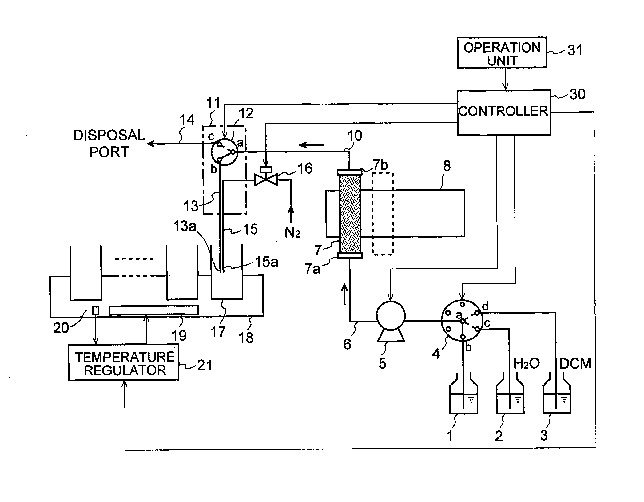
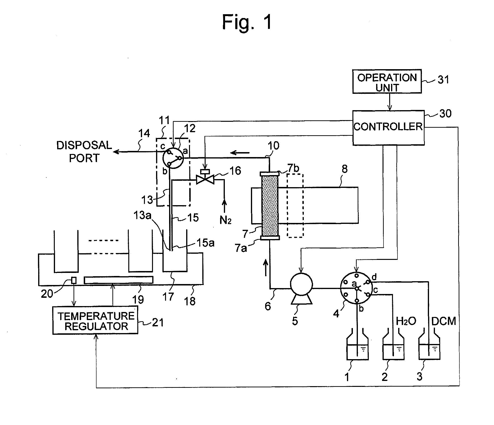
[0063]One embodiment of the preparative separation / purification system according to the present invention is hereinafter described with reference to FIGS. 1 to 5. FIG. 1 is a schematic configuration diagram of the preparative separation / purification system of the present embodiment. The present preparative separation / purification system is designed to obtain a target component in purified, solid forms from a solution containing the target component previously separated by a preparative liquid chromatograph (not shown). Alternatively, it is possible to directly connect the preparative liquid chromatograph to the upstream side of the present system so as to directly introduce a solution containing a target component separated by the preparative liquid chromatograph.

[0064]In FIG. 1, a solution container 1 holds a solution that has been separated beforehand as stated earlier. The solvent of this solution, which contains a target compound, is mainly composed of a mobile phase used in the...


PUM

PropertyMeasurementUnit
timeaaaaaaaaaa
specific gravityaaaaaaaaaa
boiling pointaaaaaaaaaa

Abstract

After a target compound is captured by an adsorbent within a trap column (7) held by a column rack (8) in a substantially vertical position and the column is filled with water to wash its inside, dichloromethane is slowly introduced from an inlet end (7a) on the lower side by a pump (5). The water within the trap column (7) is pushed upward by dichloromethane and exits from an outlet end (7b), to be disposed of via a two-way selector valve (12) and a disposal passage (14). Dichloromethane elutes the captured target compound. Therefore, when the eluate, which initially consists of water, changes via an emulsion to dichloromethane, the eluate contains an adequately high concentration of target compound. At this point, the two-way valve (12) is switched to a preparative separation passage (13). As a result, a solution that is adequately free from water and yet contains the target compound can be collected into a collection container (17), and the target compound in solid forms can be quickly obtained.

Description

TECHNICAL FIELD[0001]The present invention relates to a preparative separation / purification system for separately purifying and collecting one or more components individually extracted from a solution by a liquid chromatograph.BACKGROUND ART[0002]For example, in the pharmaceutical industry, preparative separation / purification systems utilizing liquid chromatographs are used to collect samples of a variety of chemically synthesized compounds in order to store those samples in a library or analyze them in more detail. Conventional examples of the preparative separation / purification system are disclosed in Patent Documents 1 and 2.[0003]In these conventional apparatuses, target components (compounds) in a sample solution are temporally separated by a liquid chromatograph. The separated target components are then respectively introduced into different trap columns and temporarily captured therein. Subsequently, a solvent is supplied into each trap column to quickly elute the component f...

Claims


Application Information

Patent Timeline
11 Nov 2010
Publication
US20100281958A1
IPC
G01N30/02
CPC
B01D15/24; B01D15/203; B01D15/00; G01N30/08; G01N30/26; G01N30/80
Inventors
KONO, YUTAKA; NISHIMURA, MASAYUKI