Multipoint laser doppler vibrometer

a laser doppler and vibrometer technology, applied in the field of vibration measurement, can solve problems such as increasing system cost, and achieve the effect of improving the vibration measurement system

Inactive Publication Date: 2010-11-11
DUBLIN INST OF TECH +2
View PDF7 Cites 19 Cited by
  • Summary
  • Abstract
  • Description
  • Claims
  • Application Information

AI Technical Summary

Problems solved by technology

This requires that the optical system for steering the laser beam be precisely controlled and monitored as described in JP2002221077, and significantly increases the system cost.

Method used


Image

  • Multipoint laser doppler vibrometer
  • Multipoint laser doppler vibrometer
  • Multipoint laser doppler vibrometer

Examples


Embodiment Construction

Brief Description of the Drawings

[0036]The invention will be more clearly understood from the following description of some embodiments thereof, given by way of example only with reference to the accompanying drawings in which:

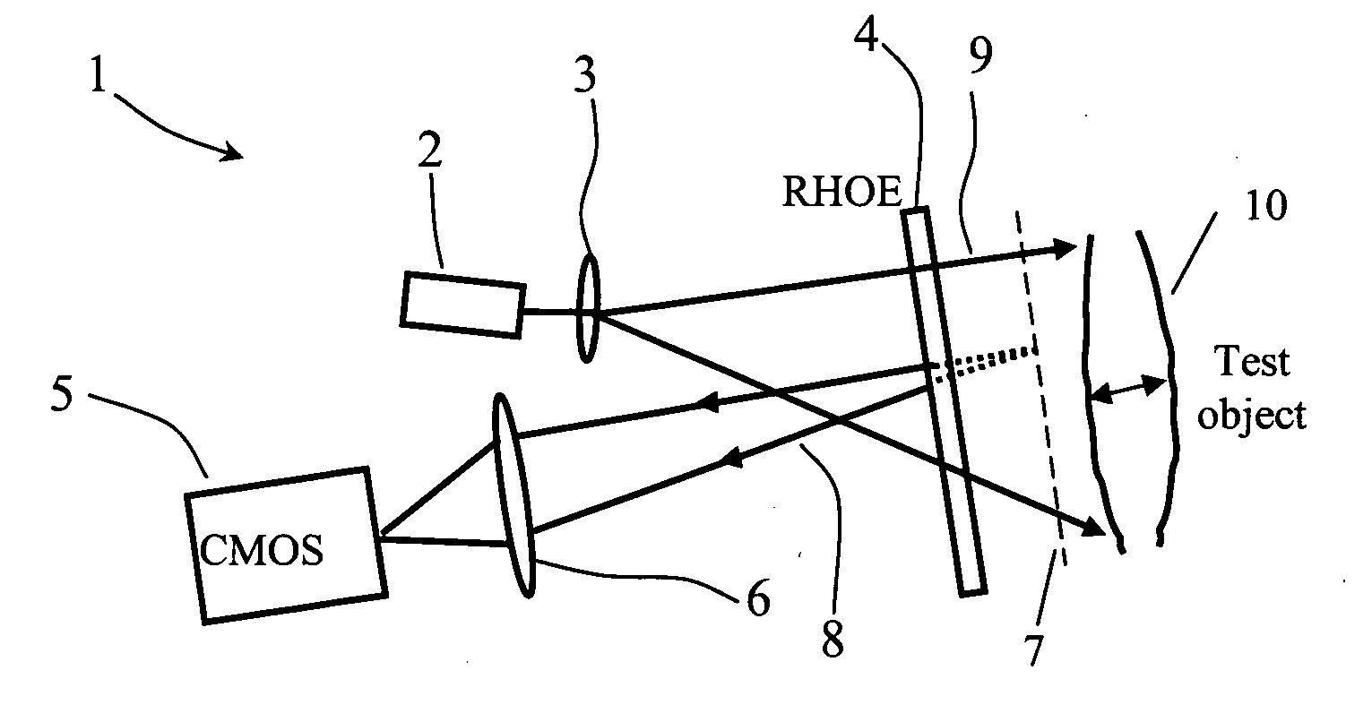
[0037]FIG. 1 is a diagram illustrating a vibration measurement system of the invention;

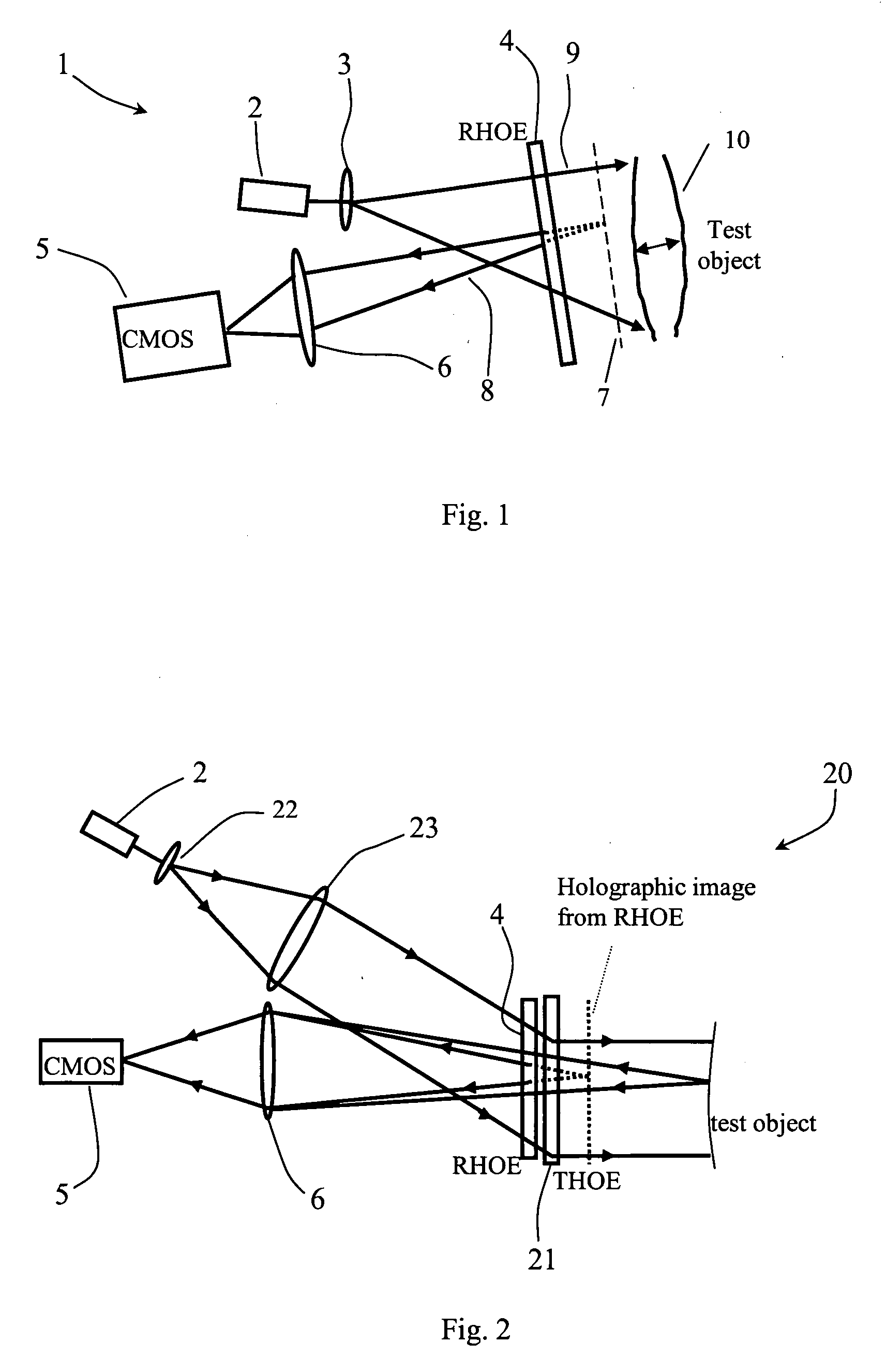
[0038]FIG. 2 is a diagram of an alternative vibration measurement system;

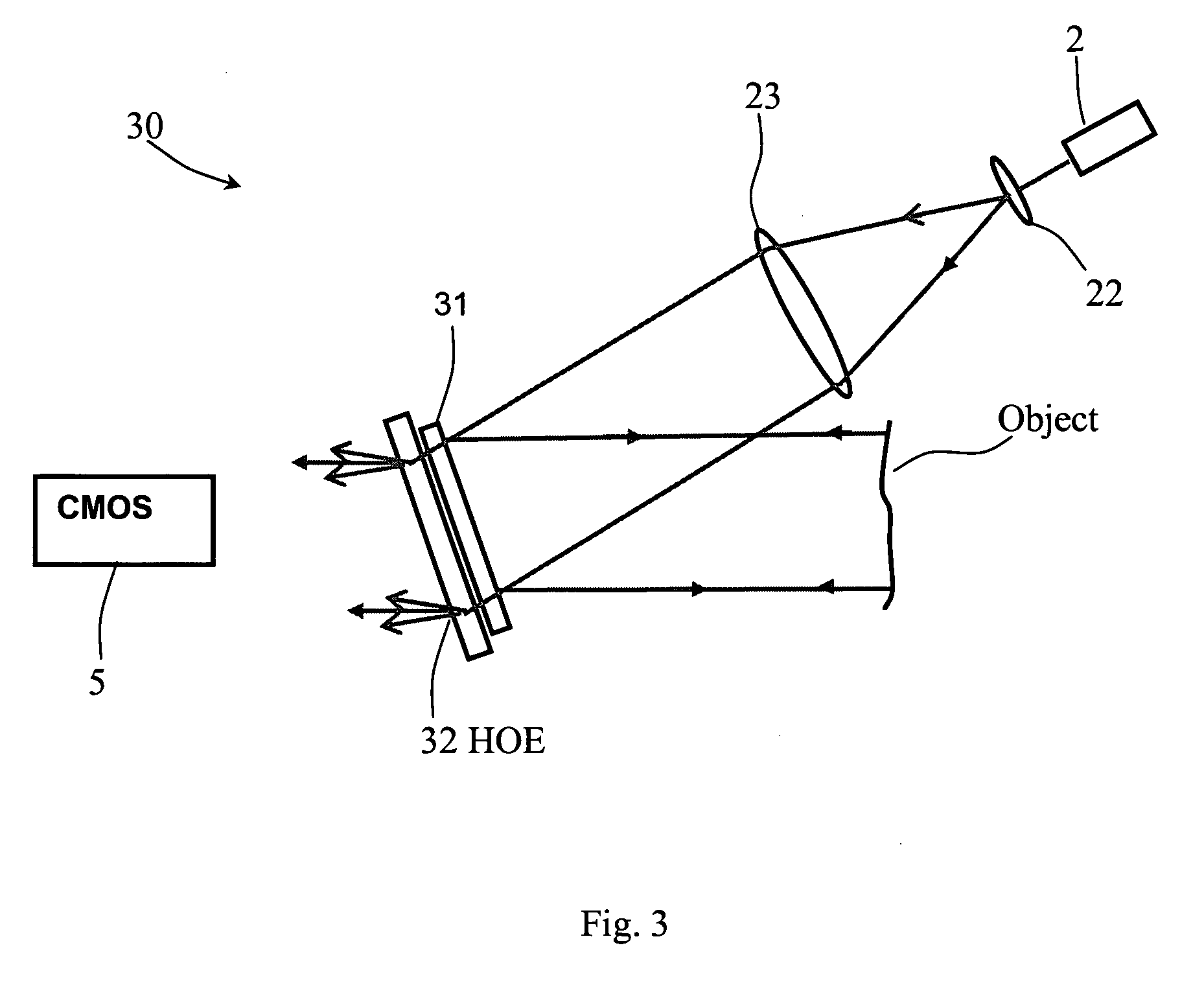
[0039]FIG. 3 is a diagram of a further alternative vibration measurement system:

[0040]FIG. 4 is a diagram a further vibration measurement system:

[0041]FIG. 5 is a display of a 2.22 kHz interferometer signal (upper trace) and drive signal (lower trace); and

[0042]FIG. 6 shows a typical screen display of a retrieved vibration spectrum.

DESCRIPTION OF THE EMBODIMENTS

[0043]Vibration measurement systems of the invention in some embodiments include:[0044]illumination by a light source which performs wavelength modulation of the emitted light according to an LDV scheme;[0045]a camera for receiving light from the...


PUM


Abstract

A multipoint laser Doppler vibrometer system (1) comprises a laser diode (2), beam expanding lens (3), a holographic optical element (HOE, 4) and a CMOS camera (5) receiving reflected light via optics (6). The HOE (4) is a hologram of a flat diffusely reflecting surface. Some light (8) is diffracted by the recorded hologram in the HOE (4) to provide a reference beam of light that is directed back towards the camera (5). Apart from some absorption the remaining light (9) continues onwards to illuminate the object The light that is reflected and scattered from the object (10) passes efficiently through the HOE (4) and interferes with the reference light (8) that is holographically reconstructed by the HOE (4) and subsequently detected by the camera (5). The beam from the laser diode (2) is divergent, which means that the sensitivity vector varies across the field of view. Thus the system is sensitive to both in-plane and out-of-plane motion of the object to an extent that depends on position of the object points. An alternative system (20) has two emission lenses (22, 23). The HOE (21) either redirects light already collimated by the lens combination (22, 23) or both redirects and collimates uncollimated light in such a way as to illuminate the object along the normal to its surface.

Description

FIELD OF THE APPLICATION[0001]The present application relates generally to the measurement of vibration.PRIOR ART DISCUSSION[0002]Laser Doppler vibrometry (“LDV”) is used in a wide variety of applications. Among these are the study of body and other panels and rotating parts (bearings, turbine blades) in air, sea and land transport vehicles as well as the evaluation of tyre, exhaust and brake pad noise. Civil engineering structures such as buildings, bridges, power station cooling towers, wind electricity generators, communications antennae and large storage vessels are routinely examined as part of the predictive maintenance schedule. Household appliances including loudspeakers, furniture and sound absorption materials are also tested. Disk drives, circuit boards, microelectromechanical components and micromachines are also studied. Other application areas are in the health and environmental sciences as well as food and food packaging quality assessment.[0003]Laser Doppler vibromet...

Claims


Application Information

Patent Timeline
Patent Type & Authority Applications(United States)
IPC IPC(8): G01H9/00
CPCG01H9/002G01H9/00
Inventor TOAL, VINCENTWHELAN, MAURICECONNELLY, MICHAELMARTIN, SUZANNEGUNTAKA, TULASI SRIDHAR REDDY
Owner DUBLIN INST OF TECH
Why Eureka
Try Eureka