
VCR universal drive

a technology of universal drive and internal combustion engine, which is applied in the direction of couplings, yielding couplings, couplings, etc., can solve the problems of large expense, complicated constructive implementation of crankshaft distribution proposed there, extra friction, etc., and achieves complete friction neutrality, free deflection, and easy flex

Inactive Publication Date: 2010-11-11
FEV
View PDF14 Cites 1 Cited by
  • Summary
  • Abstract
  • Description
  • Claims
  • Application Information

AI Technical Summary

Benefits of technology

[0032]With the embodiments proposed above, for example, it is possible to avoid extra friction in the engine operating points relevant to fuel consumption, while only slight additional friction results at the other points. This is possible with a small construction effort and low production and assembly costs.
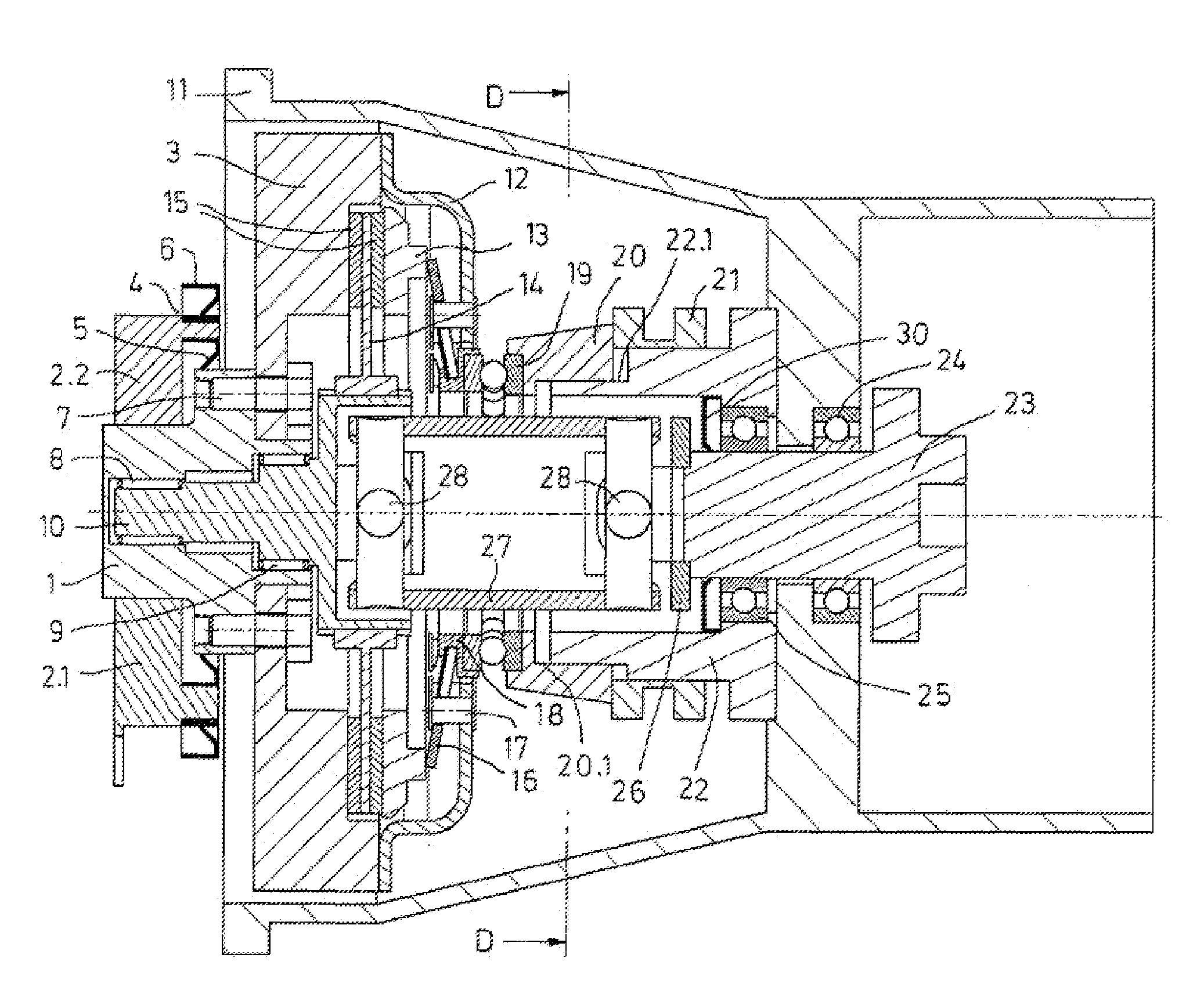
[0035]It is particularly advantageous if the engine and transmission are aligned with one another in such a manner that the crankshaft and the input transmission shaft are aligned whenever an eccentric position is adjusted that preferably corresponds to a compression setting that occurs particularly frequently when driving. This can be done, for example, by evaluating test cycles, as well as by an evaluation of the driving behavior of the vehicle user in the normal operation of a vehicle. Thus the user can be selectively recognized and a corresponding evaluation of the driving mode can be performed. For instance, it is known from engine tests that in the New European Driving Cycle (NEDC) it is possible to drive almost the entire time with maximum compression. If the crankshaft and the transmission shafts are aligned, then the articulated shaft rotates rigidly and there are no sliding or rolling movements, i.e., there is complete friction neutrality.
[0036]If a flexible shaft is used, it is easy to flex but torsionally rigid. The flexible shaft is constructed substantially rotationally rigid with respect to torques about the longitudinal axis of the shaft, but is deformable by a force in the direction of the resulting centrifugal force. The flexible shaft thus allows a freer deflection in the rotation of the shaft. In addition, the shaft is preferably symmetrically supported and also deforms symmetrically with respect to the bearing points during rotation, so that tilting of the bearings can be avoided As a result, a bending line of the shaft can be specifically influenced by providing the flexible shaft. To avoid tilting of the bearings, the bearing surfaces can be provided with a convexity. A flexible shaft is preferably used for a transaxle drive.

Problems solved by technology

It is disadvantageous that slipping and rolling motions occur in both variants, which leads to extra friction.
A constructive implementation of the crankshaft distribution proposed there is complicated and requires a large expense.

Method used


Image

  • VCR universal drive
  • VCR universal drive
  • VCR universal drive

Examples


Embodiment Construction

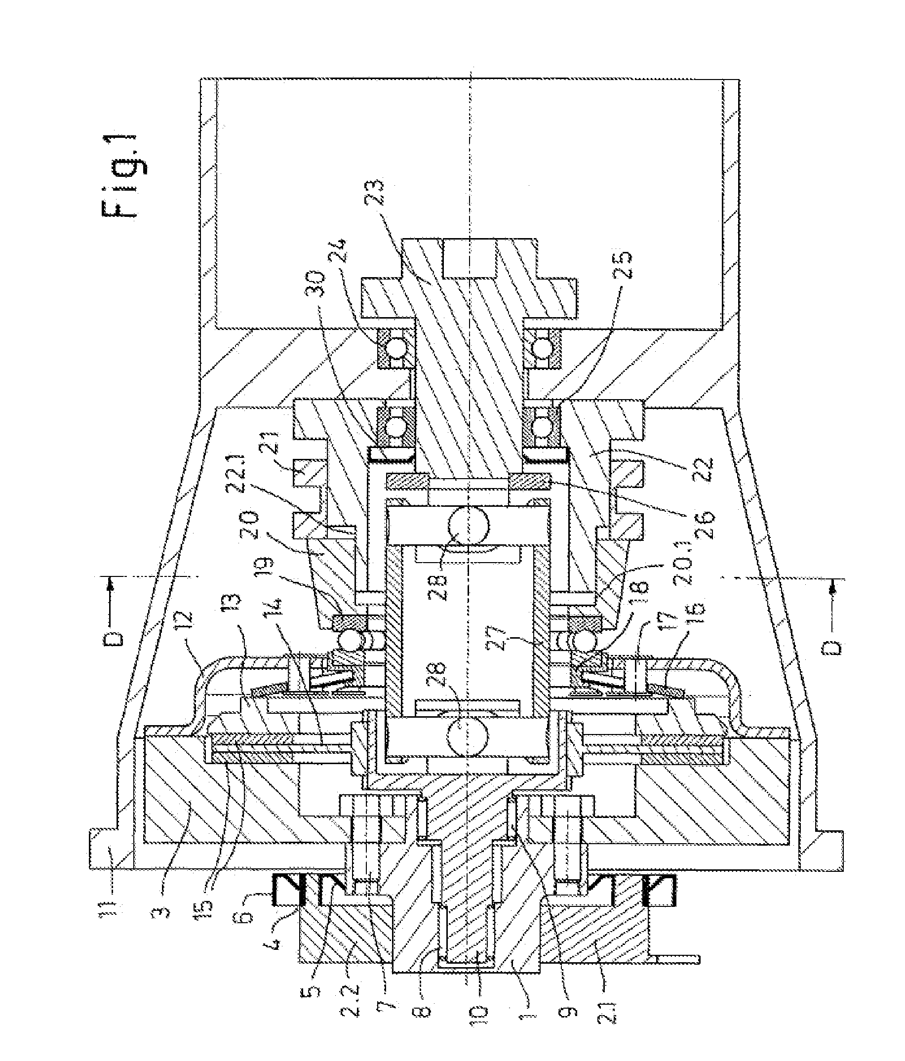
[0044]A configuration, which is exemplary but not limiting, will be presented in detail with reference to the figures.

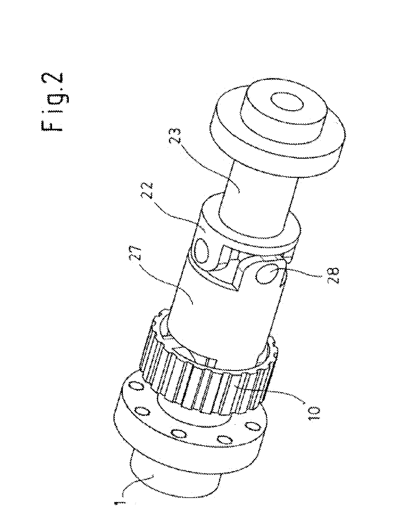
[0045]The flywheel 3 and the crankshaft 1 are nonpositively connected by means of bolts 7. The crankshaft is supported according to this configuration in cams 2, which usually have a divided design. Undivided cams can also be used, however. The articulated shaft connection can be represented by different machine elements:

[0046]cardan joints

[0047]constant velocity joints (homokinetic joints)

[0048]tripod joints

[0049]curved-tooth gear couplings

[0050]Since the shafts to be connected are axially parallel, the articulated shaft consists of two joints. Another configuration provides that three or four joints are used, particularly in case axial parallelism is absent.

[0051]The front joint 10 is supported by means of the two bearings 8 and 9 statically in the crankshaft. The rear joint 26 is supported by means of the two bearings 24 and 25 statically at the transmission. It i...


PUM


Abstract

An internal combustion engine with a variable compression ratio is provided. The engine can have a crankshaft that is pivotably supported, a flywheel fixed on the crankshaft, and a connection shaft that is arranged between the crankshaft and an input shaft of a shift transmission.

Description

CROSS-REFERENCE TO RELATED APPLICATION[0001]This application is the U.S. National Phase of PCT / EP2008 / 011136 filed Dec. 30, 2008, which claims priority of German Patent Application 10 2008 003 109 / 7 filed Dec. 31, 2007, both of which are incorporated herein in their entirety by reference.FIELD OF THE INVENTION[0002]The present invention relates to an internal combustion engine and a drivetrain, preferably both for a motor vehicle, in particular, a road vehicle. The internal combustion engine is preferably a multicylinder internal combustion engine, in particular a 3-, 4-, 5- or 6-cylinder engine.[0003]The objective of the invention is to compensate for the axial offset of the crankshaft to the transmission input shaft for VCR engines with eccentric support of the crankshaft.BACKGROUND OF THE INVENTION[0004]In the prior art for eccentric crankshaft displacement, either parallel crank transmissions or a spur gear / ring gear transmission stage have been proposed as possibilities for com...

Claims


Application Information

Patent Timeline
Patent Type & Authority Applications(United States)
IPC IPC(8): F02B75/04F16D3/00
CPCF02B75/047F16D23/148F16D23/14
Inventor WITTEK, KARSTEN
Owner FEV
Learn More