Dual-polarized dual-band broad beamwidth directive patch antenna

a patch antenna and beamwidth directive technology, applied in the field of radio communication antenna systems, can solve the problems of inability to achieve the beam broadening effect, difficulty in implementing techniques at frequencies below 1 ghz, and inability to achieve the effect of beam broadening effect,

Inactive Publication Date: 2010-11-11
INTEL CORP
View PDF3 Cites 64 Cited by
  • Summary
  • Abstract
  • Description
  • Claims
  • Application Information

AI Technical Summary

Problems solved by technology

Real world applications often call for an antenna radiating element with frequency bandwidth, pattern beamwidth and polarization requirements that may not be possible for conventional antenna radiating element designs to achieve due to overall mechanical constraints.
These techniques are effective for broadening the beamwidth for high frequency bands (1.7 GHz-2.2 GHz); however, these techniques are either not effective or are difficult to implement at frequencies below 1 GHz.
At lower frequencies (i.e., longer wavelength), the thickness of the dielectric shroud becomes impractically large to achieve the beam broadening effect.

Method used


Image

  • Dual-polarized dual-band broad beamwidth directive patch antenna
  • Dual-polarized dual-band broad beamwidth directive patch antenna
  • Dual-polarized dual-band broad beamwidth directive patch antenna

Examples


Embodiment Construction

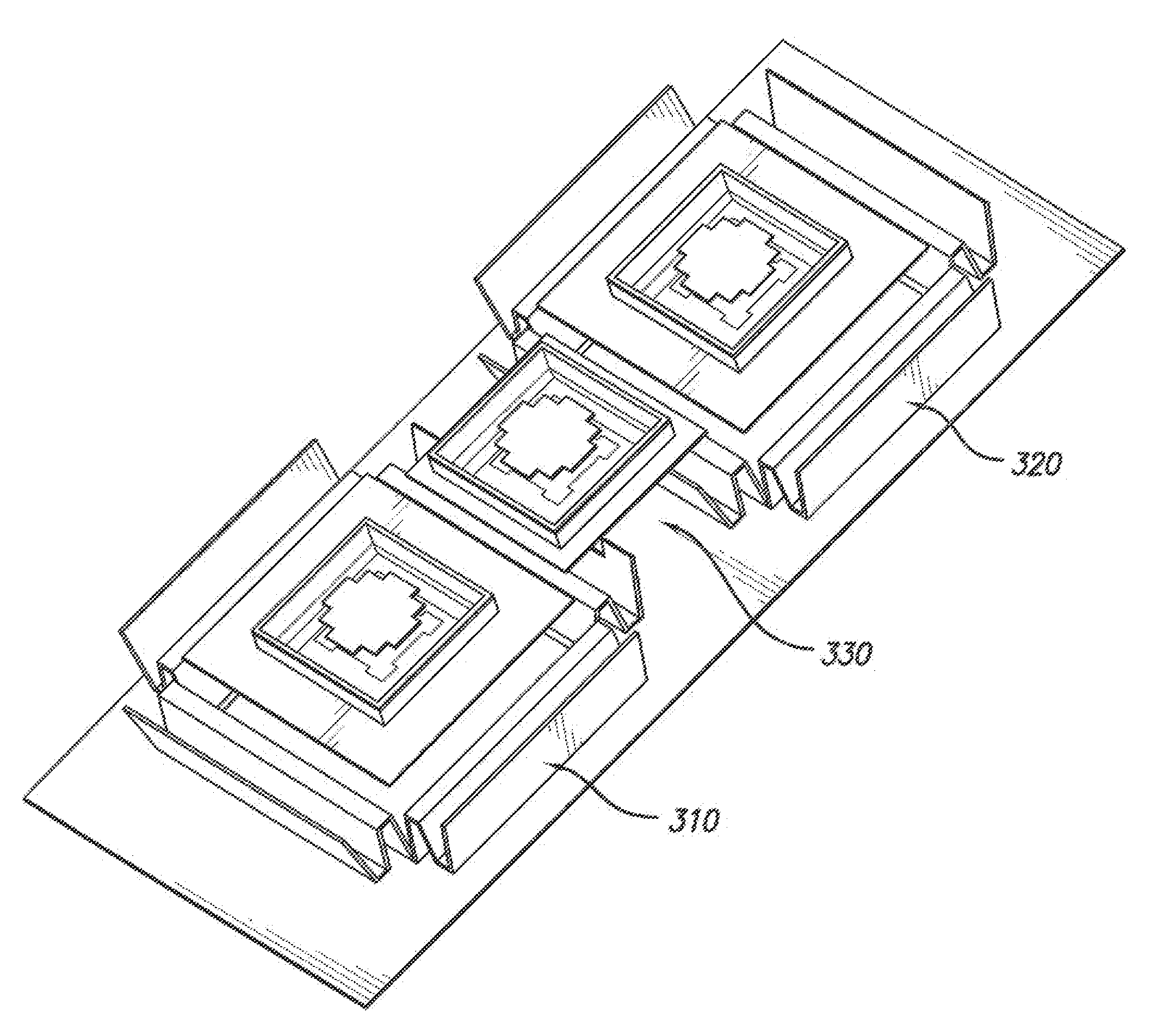
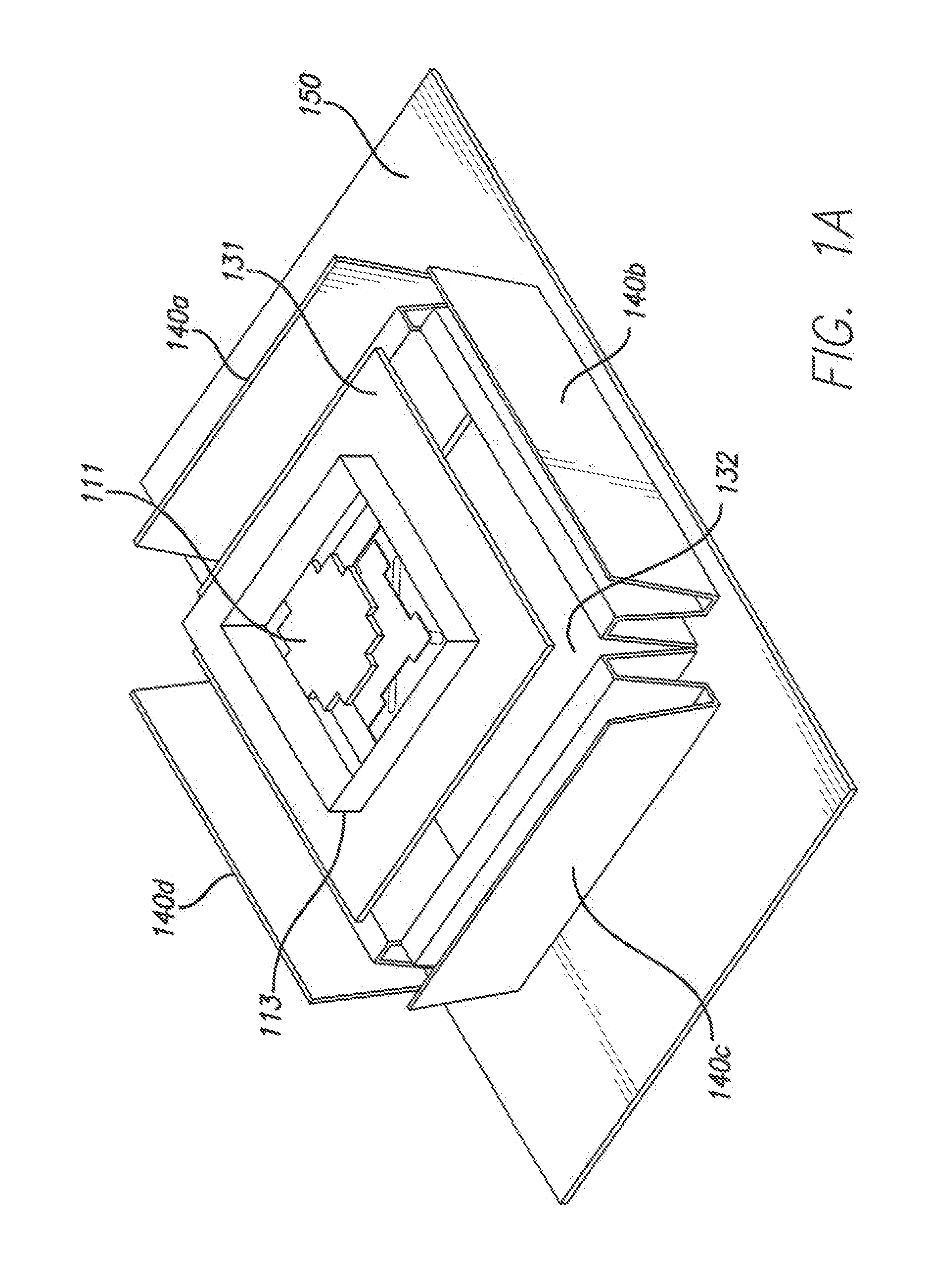
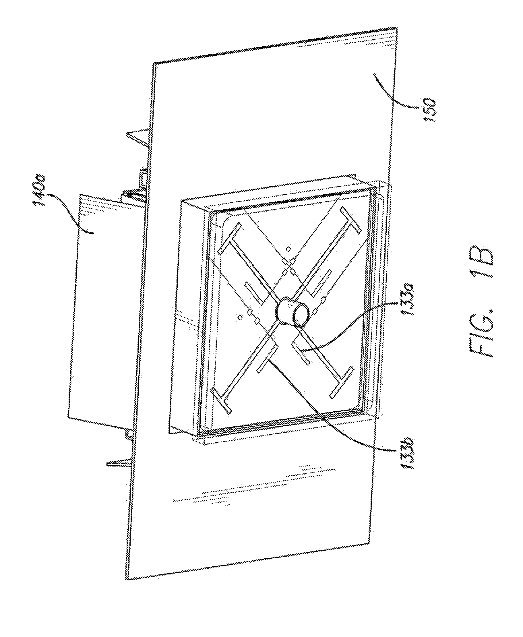
[0024]It is an object of the present invention to provide dual-band antennas that emit radiation having a broad beamwidth while achieving a large frequency bandwidth of operation. The disclosed antenna structure produces broad radiation patterns with typical half power beamwidth of 90 degrees in the azimuth direction at two separate frequency bands with low cross-polarized field components.

[0025]In an embodiment of the present invention, a dual-band antenna structure comprises a high frequency patch antenna cavity stacked inline above a low frequency patch antenna cavity. Both the high frequency patch antenna and the low frequency patch antenna employ two patches in order to achieve a wide frequency bandwidth that is typically 25% of the emission frequency. In a preferred embodiment, a four-sided N-shaped metallic wall surrounds the low frequency patch antenna cavity and broadens the emission radiation beamwidth of the low frequency emission. As such, these dual band antenna structu...


PUM


Abstract

An antenna architecture with a dual-band patch antenna structure having a broadened low-frequency beamwidth is disclosed. The dual band antenna structure comprises a high frequency patch antenna cavity stacked inline above a low frequency patch antenna cavity. An N-shaped metallic wall surrounds the low frequency patch antenna cavity and broadens the emission radiation beamwidth of the low frequency emission. As such, these dual band antenna structures can emit radiation with a beamwidth of approximately 90 degrees in the low frequency band of 700 MHz to 900 MHz as well as the high frequency band of 1.7 GHz to 2.2 GHz.

Description

RELATED APPLICATION INFORMATION[0001]The present application claims priority under 35 USC Section 119(e) to U.S. provisional patent application Ser. No. 61 / 167,097 filed Apr. 6, 2009, the disclosure of which is incorporated herein by reference in its entirety.BACKGROUND OF THE INVENTION[0002]1. Field of the Invention[0003]The present invention relates to radio communication antenna systems for wireless networks. More particularly, the invention is directed to active array antennas and related methods.[0004]2. Description of the Prior Art And Related Background Information[0005]Modern wireless antenna systems generally include a plurality of radiating elements that may be arranged over a ground plane defining a radiated (and received) signal beamwidth and azimuth angle. Antenna beamwidth has been conventionally defined by Half Power Beam Width (“HPBW”) of the azimuth or elevation beam relative to a bore sight of such antenna element.[0006]Real world applications often call for an ant...

Claims


Application Information

Patent Timeline
Patent Type & Authority Applications(United States)
IPC IPC(8): H01Q5/00H01Q1/42H01Q5/42
CPCH01Q9/0414H01Q5/42H01Q15/18
Inventor FOO, SENGLEE
Owner INTEL CORP
Why Eureka
Try Eureka