High efficiency backlight assembly for flat panel display assembly and method for the manufacture thereof

a flat panel display and high-efficiency technology, applied in the field of high-efficiency backlight assembly for flat panel display assembly, can solve the problems of increasing the cost of large-scale manufacturing, relatively expensive production of thermoplastic resin coatings, etc., and achieve the effect of increasing the reflectivity of the light cavity

Active Publication Date: 2010-11-11
HONEYWELL INT INC
View PDF9 Cites 9 Cited by
  • Summary
  • Abstract
  • Description
  • Claims
  • Application Information

AI Technical Summary

Benefits of technology

[0005]A backlight assembly is provided for deployment within a flat panel display assembly. In one embodiment, the backlight assembly includes a printed wiring board (PWB), a casing sidewall, a plurality of light emitting diodes (LEDs), a reflective solder mask, and a first reflective silkscreen layer. The PWB includes a display-facing surface, and the casing sidewall disposed is around a peripheral portion of the PWB and cooperates with the display-facing surface to define a light cavity. The plurality of LEDs is electrically coupled to the PWB and illuminates the light cavity when energized. The reflective solder mask overlays the display-facing surface of the PWB, and the first reflective silkscreen layer overlays the reflective solder mask. The first white silkscreen layer cooperates with the reflective solder mask to increase the reflectivity of the light cavity over the visible color spectrum.
[0006]A method is also provided for manufacturing a backlight assembly suitable for deployment within a flat panel display assembly. In one embodiment, the method includes the steps of: (i) fabricating a printed wiring board (PWB) having a display-facing surface, (ii) disposing a casing sidewall around the PWB to create light cavity within the backlight assembly, (iii) electrically coupling a plurality of light emitting diodes (LEDs) to the PWB, (iv) depositing a reflective solder mask over the display-facing surface of the PWB, and (v) applying a first reflective silkscreen layer over the reflective solder mask utilizing a silkscreen process. The first reflective silkscreen layer cooperates with the reflective solder mask to increase the reflectivity of the light cavity over the visible color spectrum.

Problems solved by technology

Although providing a considerable increase in the reflectivity of the display-facing surface, such known thermoplastic resin coatings tend to be relatively expensive to produce and can add considerable cost in large scale manufacturing.

Method used


Image

  • High efficiency backlight assembly for flat panel display assembly and method for the manufacture thereof
  • High efficiency backlight assembly for flat panel display assembly and method for the manufacture thereof
  • High efficiency backlight assembly for flat panel display assembly and method for the manufacture thereof

Examples


Embodiment Construction

[0012]The following Detailed Description is merely exemplary in nature and is not intended to limit the invention or the application and uses of the invention. Furthermore, there is no intention to be bound by any theory presented in the preceding Background or the following Detailed Description. Although the following describes an exemplary embodiment of a highly reflective backlight assembly deployed within a liquid crystal display (LCD) assembly, it will be appreciated that embodiments of the highly reflective backlight assembly are suitable for employment within various types of flat panel display assemblies requiring rear or side illumination. Such flat panel display assemblies include, but are not limited to, plasma-based display assemblies and organic light-emitting diode (OLED) display assemblies.

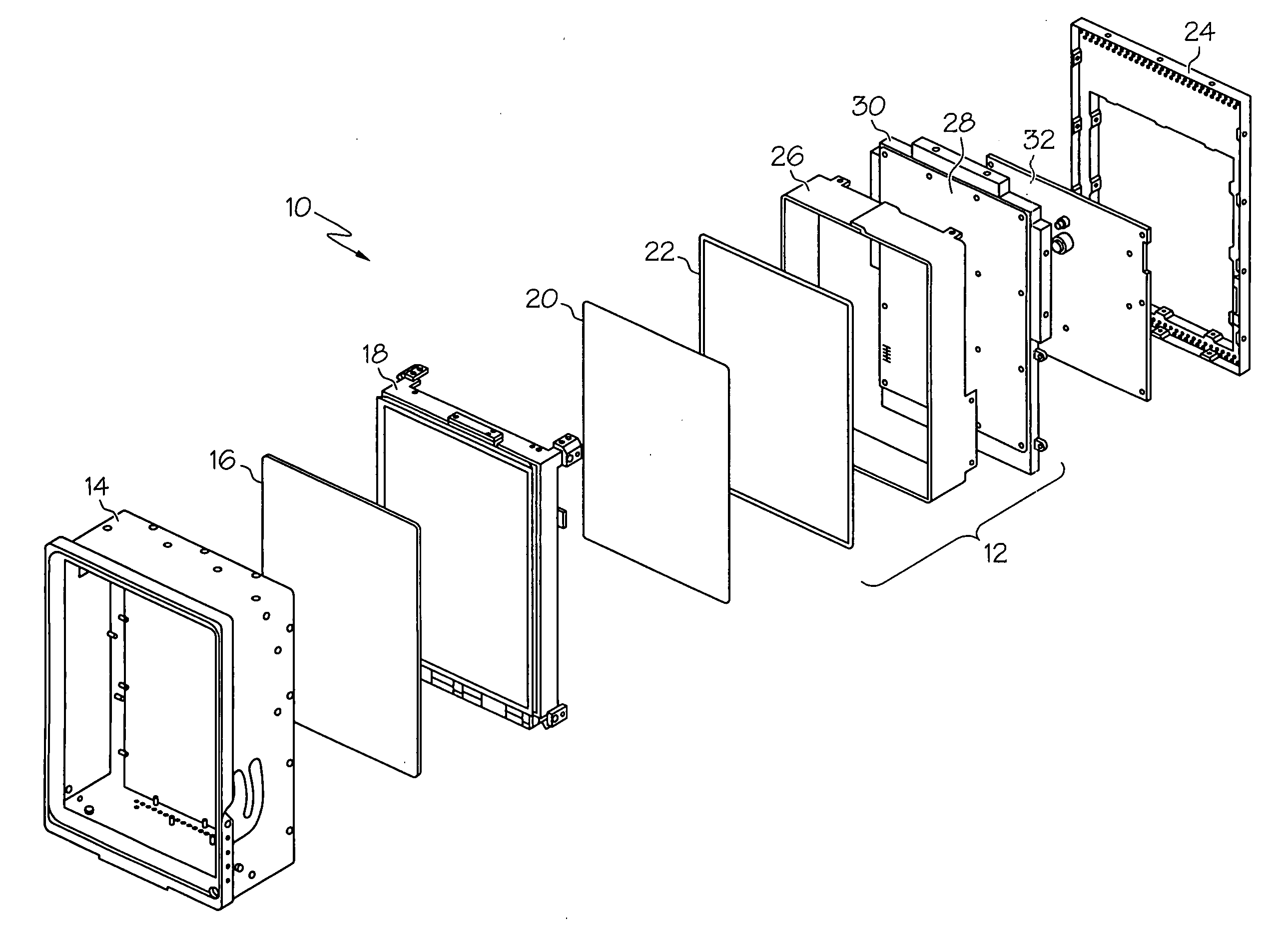
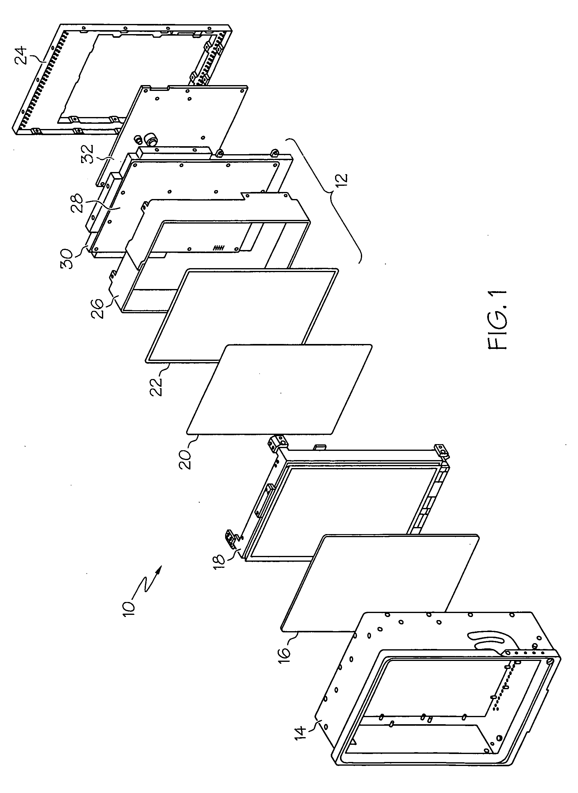
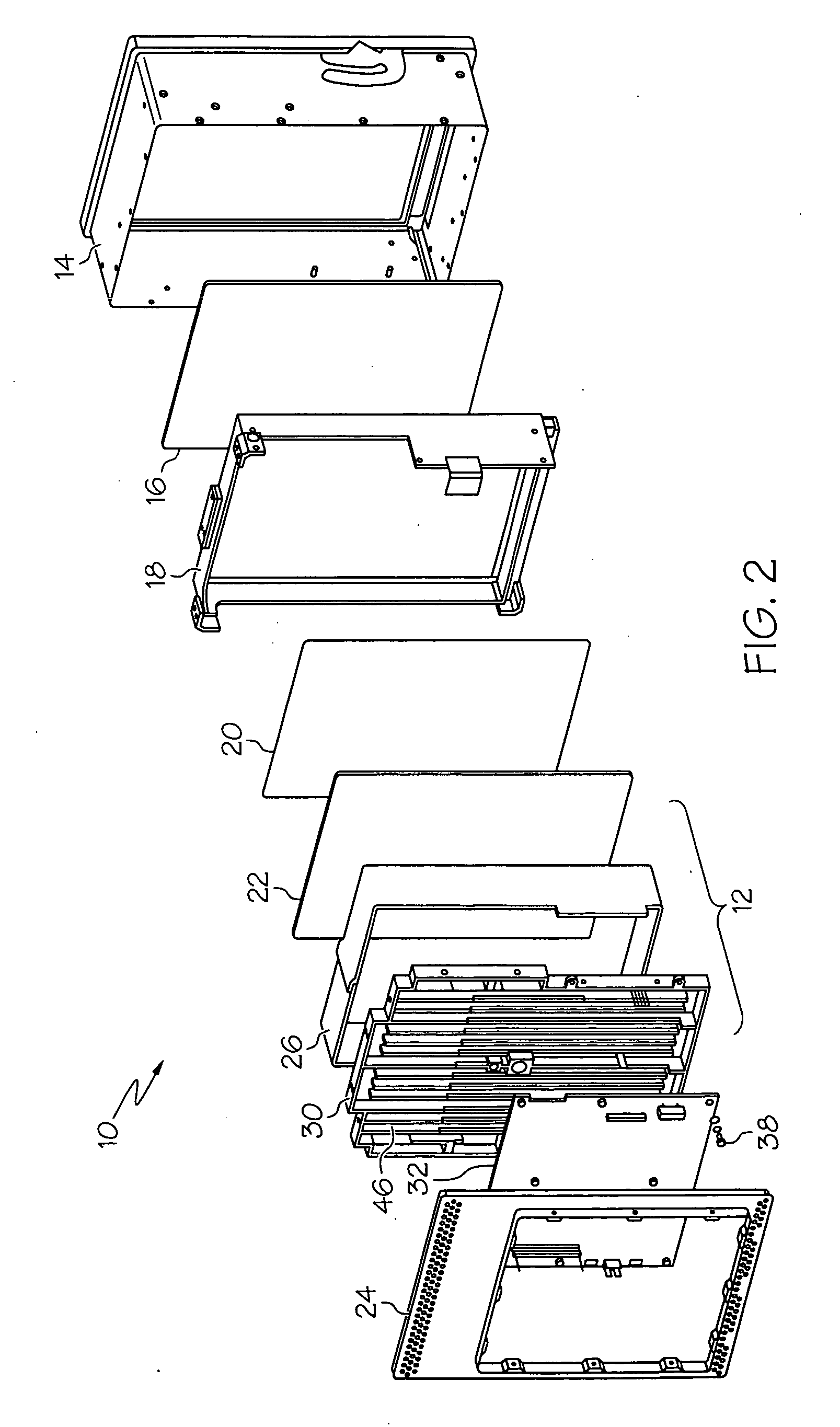
[0013]FIGS. 1 and 2 are front and rear exploded views, respectively, of a liquid crystal display (LCD) assembly 10 including a highly efficient backlight assembly 12 in accordance w...


PUM

PropertyMeasurementUnit
reflectivityaaaaaaaaaa
coloraaaaaaaaaa
visible coloraaaaaaaaaa

Abstract

A backlight assembly is provided for deployment within a flat panel display assembly. In one embodiment, the backlight assembly includes a printed wiring board (PWB), a casing sidewall, a plurality of light emitting diodes (LEDs), a reflective solder mask, and a first reflective silkscreen layer. The PWB includes a display-facing surface, and the casing sidewall disposed is around a peripheral portion of the PWB and cooperates with the display-facing surface to define a light cavity. The plurality of LEDs us electrically coupled to the PWB and illuminates the light cavity when energized. The reflective solder mask overlays the display-facing surface of the PWB, and the first reflective silkscreen layer overlays the reflective solder mask. The first reflective silkscreen layer cooperates with the reflective solder mask to increase the reflectivity of the light cavity over the visible color spectrum.

Description

TECHNICAL FIELD[0001]The present invention relates generally to display devices and, more particularly, to a high efficiency backlight assembly suitable for deployment within a flat panel display assembly, such as a liquid crystal display assembly.BACKGROUND[0002]A generalized liquid crystal display (LCD) assembly includes an LCD (e.g., one or more glass substrates carrying a number of electrodes and liquid crystals), which is disposed between a transparent display cover and a backlight assembly. The backlight assembly typically includes a driver board, a casing sidewall, a light source, and a heat sink. The casing sidewall circumscribes the driver board and cooperates therewith to create a light cavity within the LCD assembly. The light source is electrically coupled to the driver board and, when energized, illuminates the light cavity to backlight the LCD. The light source can assume a variety of different forms including that of an incandescent bulb, an electroluminescent panel, ...

Claims


Application Information

Patent Timeline
Patent Type & Authority Applications(United States)
IPC IPC(8): G02F1/13357G09F13/04H01J9/24
CPCG02F1/133603G02F1/133605G02F2001/133331G09F13/22G02F2201/503G09F9/33G09F9/35G02F2001/133612G02F1/133331G02F1/133612G02F1/133514G02F1/133553G02F1/133608G02F1/133621
Inventor SCHAEFFER, MARTINANDERSON, JOHNPAMPERIN, STEPHEN J.
Owner HONEYWELL INT INC
Why Eureka
Try Eureka