Short coherence interferometer

a coherence interferometer and short technology, applied in the field of short coherence interferometer apparatus, can solve the problems of multiple different axially spaced regions, difficult to distinguish optical coherence tomography, etc., and achieve the effects of preventing interactions between multiple strong reference signals, high signal sensitivity, and advantageous structural simplification

Active Publication Date: 2010-11-11
CARL ZEISS MEDITEC AG
View PDF18 Cites 51 Cited by
  • Summary
  • Abstract
  • Description
  • Claims
  • Application Information

AI Technical Summary

Benefits of technology

[0012]The invention thus employs an interferometer having only one reference arm. This not only results in an advantageous structural simplification. Additionally, a high signal sensitivity is achieved in combination of balanced detection and multiple measuring arms and one common reference arm, because interactions between multiple strong reference signals are prevented. Such interactions would result in strong and wide-ranging artifacts. In the concept according to the invention, at most an interaction of two weak signals occurs, namely the signals from the measuring arms. An interaction of two strong reference signals is avoided.
[0013

Problems solved by technology

Optical coherence tomography, in particular in the form of FD OCDR, is problematic in the fixed linkage of measuring area and measuring resolution.
Finally, US 2006/0109477, which was already cited at the beginning, does not allow multiple di

Method used


Image

  • Short coherence interferometer
  • Short coherence interferometer
  • Short coherence interferometer

Examples


Embodiment Construction

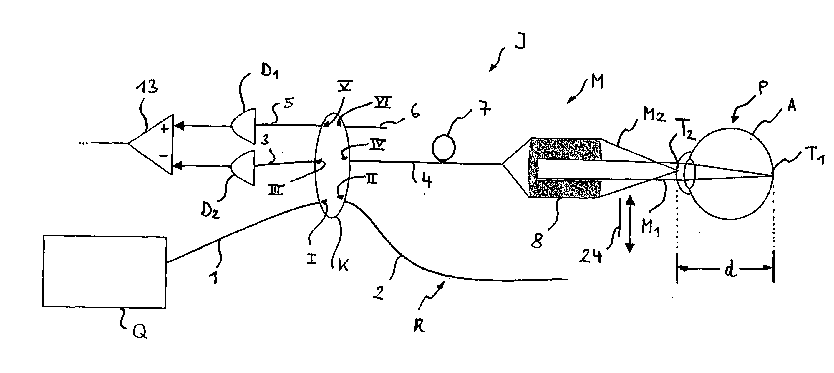
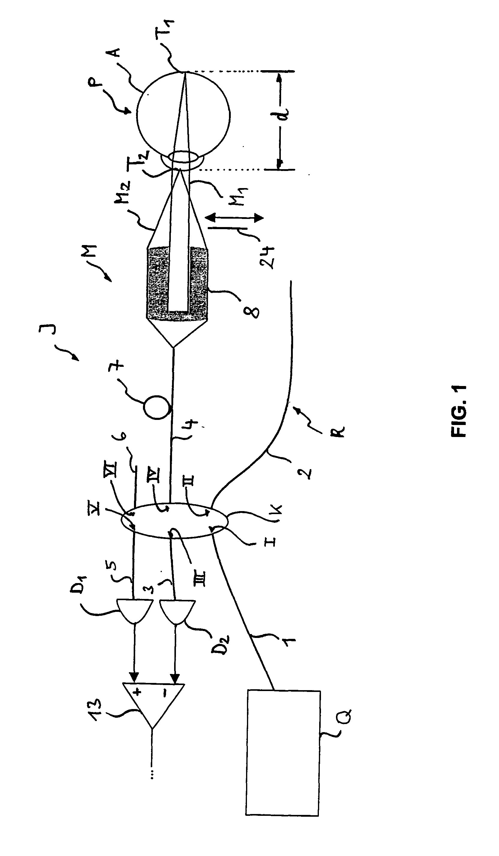
[0066]FIG. 1 schematically shows an interferometer for SS OCDR. Radiation from a beam source Q, which is swept and has a line width of less than 30 pm, for example, preferably ≦26 pm or in another embodiment preferably 1and T2 on a specimen P, which is an eye A in the example embodiment. Instead of an eye, of course, any arbitrary, non-biological technical structure may also be detected using the interferometer I, because the interferometer I generally detects the location and scattering intensity of scattering centers which are in the subregions T1 and T2. Insofar as the present description thus makes reference to the application on an eye A, this is purely exemplary and is not to be understood as restrictive.

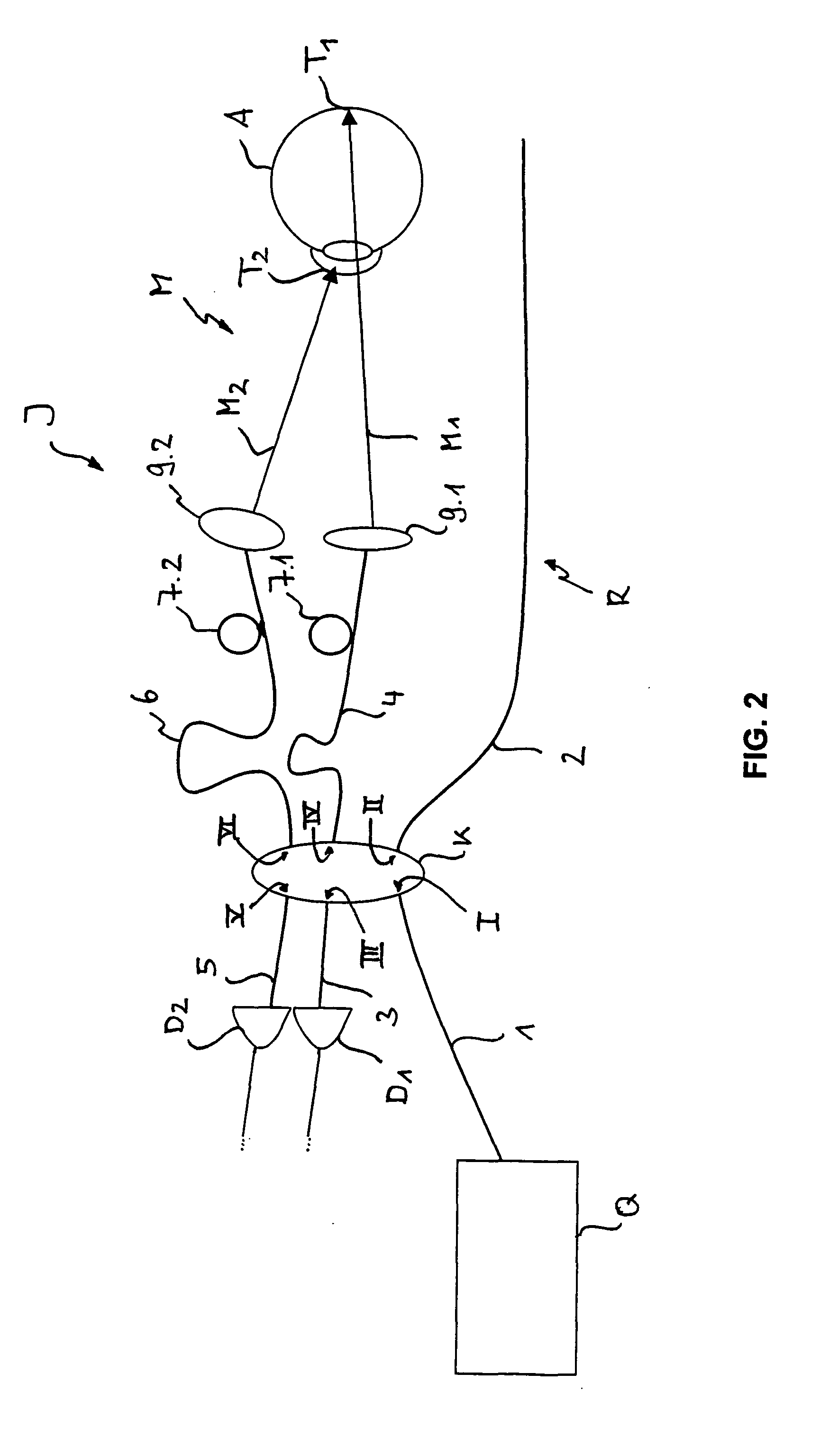
[0067]The subregions T1 and T2 are shown as points in FIGS. 1 and 2. This is only used for a better overview. Due to the sweeping of the radiation source Q, the subregions extend over a range which extends along the axis of incidence of the radiation, of course. However, the m...


PUM


Abstract

A short coherence interferometer apparatus for measuring multiple axially spaced regions of a specimen, in particular the eye, which has at least one measuring beam path, through which multiple individual measuring beams are incident on the specimen, and one reference beam path, through which a reference beam runs, with which the individual measuring beams are superimposed and brought into interference. The individual measuring beams are axially offset to one another upon incidence on the specimen by an amount which is adapted to the axial spacing. The interferometer apparatus superimposes each individual measuring beam with the reference beam in an interfering manner and conducts it to a detector associated with the particular individual measuring beam. The individual measuring beams are combined into a mixture in which they have varying phasing in the superposition with the reference beam.

Description

PRIORITY CLAIM[0001]The present application is a National Phase entry of PCT Application No. PCT / EP2008 / 008230, filed Sep. 26, 2008, which claims priority from German Application Number 102007046507.8, filed Sep. 28, 2007, the disclosures of which are hereby incorporated by reference herein in their entirety.FIELD OF THE INVENTION[0002]The invention relates to a short coherence interferometer apparatus for measuring multiple axially spaced regions of a specimen, in particular the eye, which apparatus has at least one measuring beam path, through which multiple individual measuring beams are incident on the specimen, and one reference beam path, through which reference radiation is guided, which is superimposed with the individual measuring beams and is brought into interference with the individual measuring beams, wherein the individual measuring beams are axially offset to one another upon incidence on the specimen by an amount which is adapted to the axial spacing, and wherein the...

Claims


Application Information

Patent Timeline
IPC IPC(8): G01B9/02
CPCA61B3/1005A61B3/102A61B3/113G01N21/4795G01N2021/1787G01B2290/45G01B9/02021G01B9/02035G01B9/02091G01B2290/70G01B9/02081G01B9/02028
Inventor HACKER, MARTIN
Owner CARL ZEISS MEDITEC AG
Why Eureka
Try Eureka