
Inflatable wind turbine

Inactive Publication Date: 2010-11-11
FLODESIGN WIND TURBINE
View PDF14 Cites 20 Cited by
  • Summary
  • Abstract
  • Description
  • Claims
  • Application Information

AI Technical Summary

Benefits of technology

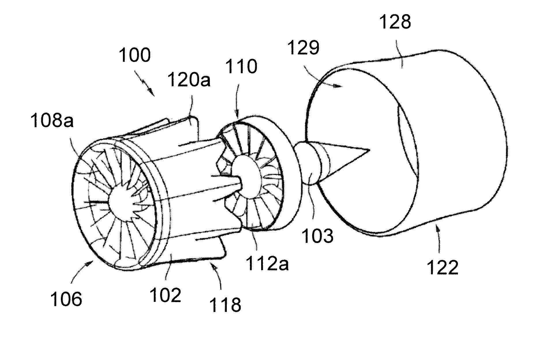
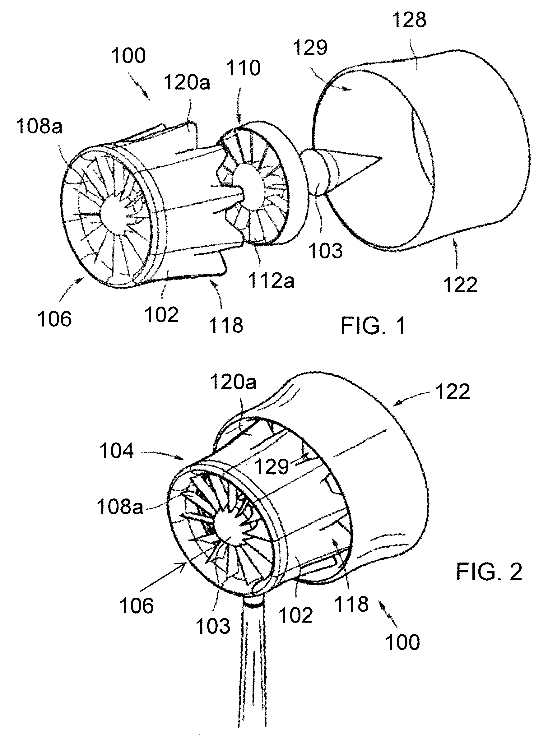
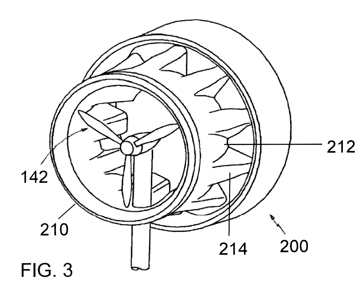
[0007]The present disclosure describes wind turbines of reduced mass and size. In particular, the wind turbines include a turbine shroud and / or ejector shroud having inflatable components. Such wind turbines are lighter. An inflated shroud would allow the turbine to change its aerodynamics / shape to accommodate changes in fluid flow. It would also allow for less substantial supports in the turbine body, and also allow the inflated portions to be deflated if needed due to adverse weather conditions. The inflated portions of the turbine do not actively rotate to aid in energy extraction or power production. The inflated portions may be covered by an exterior skin and / or an interior skin. The skins may add strength, water resistance, ultra violet (UV) stability, and other functionality.

Problems solved by technology

Although HAWTs have achieved widespread usage, their efficiency is not optimized.
Several problems are associated with HAWTs in both construction and operation.
The tall towers and long blades are difficult to transport.
Very tall and expensive cranes and skilled operators are needed for installation.
HAWTs are difficult to operate in near ground, turbulent winds.
Ice build-up on the nacelle and the blades can cause power reduction and safety issues.
Their height also makes them obtrusively visible across large areas, disrupting the appearance of the landscape and sometimes creating local opposition.
Finally, downwind variants suffer from fatigue and structural failure caused by turbulence.

Method used


Image

  • Inflatable wind turbine
  • Inflatable wind turbine
  • Inflatable wind turbine

Examples


Embodiment Construction

[0047]A more complete understanding of the components, processes, and apparatuses disclosed herein can be obtained by reference to the accompanying figures. These figures are merely schematic representations based on convenience and the ease of demonstrating the present development and are, therefore, not intended to indicate the relative size and dimensions of the devices or components thereof and / or to define or limit the scope of the exemplary embodiments.

[0048]Although specific terms are used in the following description for the sake of clarity, these terms are intended to refer only to the particular structure of the embodiments selected for illustration in the drawings and are not intended to define or limit the scope of the disclosure. In the drawings and the following description below, it is to be understood that like numeric designations refer to components of like function.

[0049]The modifier “about” used in connection with a quantity is inclusive of the stated value and h...


PUM


Abstract

A wind turbine has an impeller surrounded by a shroud. The shroud is formed from inflatable components extending between two rigid structural members. When inflated, the shroud acts to increase the energy generated by the impeller. Under adverse wind conditions, the inflatable components can be deflated to reduce surface area and wind load on the turbine.

Description

BACKGROUND[0001]This application claims priority to U.S. Provisional Patent Application Ser. No. 61 / 183,749, filed Jun. 3, 2009. This application is also a continuation-in-part application of U.S. patent application Ser. No. 12 / 555,446, filed Sep. 8, 2009, which claims priority from U.S. Provisional Patent Application Ser. No. 61 / 191,358, filed on Sep. 8, 2008. This application is also a continuation-in-part from U.S. patent application Ser. No. 12 / 054,050, filed Mar. 24, 2008, which claimed priority from U.S. Provisional Patent Application Ser. No. 60 / 919,588, filed Mar. 23, 2007. The disclosure of these applications is hereby fully incorporated by reference in their entirety.[0002]The present disclosure relates to wind turbines having inflatable components.[0003]Conventional wind turbines used for power generation generally have two to five open blades arranged like a propeller, the blades being mounted to a horizontal shaft attached to a gear box which drives a power generator. S...

Claims


Application Information

Patent Timeline
IPC IPC(8): F03D1/04F03D11/00
CPCF03D1/04F05B2240/13F05B2240/133Y02E10/72F05B2240/98F05B2250/182F05B2260/601F05B2240/922Y02E10/728F03D13/20
Inventor PRESZ, JR., WALTER M.WERLE, MICHAEL J.KENNEDY, III, THOMAS J.KEELEY, WILLIAM SCOTT
Owner FLODESIGN WIND TURBINE
Learn More