Ultrasound diagnosis apparatus

a technology of ultrasound and diagnostic equipment, applied in the field of ultrasound diagnosis equipment, can solve the problems of affecting the image pattern of the image received from a plurality of subject tissues adjacent to each other, affecting the image quality of the image, so as to reduce the noise and speckle

Active Publication Date: 2010-11-11
TOSHIBA MEDICAL SYST CORP
View PDF7 Cites 50 Cited by
  • Summary
  • Abstract
  • Description
  • Claims
  • Application Information

AI Technical Summary

Benefits of technology

[0036]To be specific, an object of the present invention is to provide a technique of, by using a process without occurrence of a time phase delay, reducing noise and speckle in the temporal direction and emphasizing a tissue part in an ultrasound image of a strenuous tissue.

Problems solved by technology

Signals received from a plurality of subject tissues adjacent to each other interfere with each other because having different phases.
This interference makes a vision different from when only amplitudes are composed, and generates a speckled image pattern.
This speckle prevents accurate observation of the position and shape of the boundary of the subject tissues.
Therefore, for a strenuously moving tissue such as the diaphragm and the heart, there is a problem that, in a superimposed image, each image of the strenuously moving tissue remains like an afterimage and blur or the like occurs.
Therefore, there is a problem that the process gets slow.
Therefore, such a method of performing the noise reduction process with respect to only the spatial direction may cause noise and speckle in an image with respect to the temporal direction.
Further, in a case that the filtering process with respect to the space is applied as it is, there is a problem that a time-phase delay occurs and an image immediately after generated (a real-time image) cannot be displayed.

Method used


Image

  • Ultrasound diagnosis apparatus
  • Ultrasound diagnosis apparatus
  • Ultrasound diagnosis apparatus

Examples


first embodiment

[0049]An ultrasound diagnosis apparatus according to a first embodiment of the present invention will be described below.

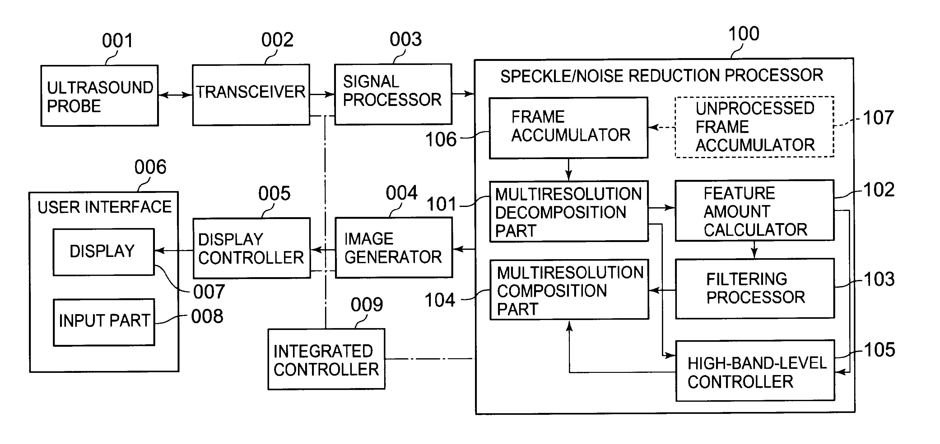
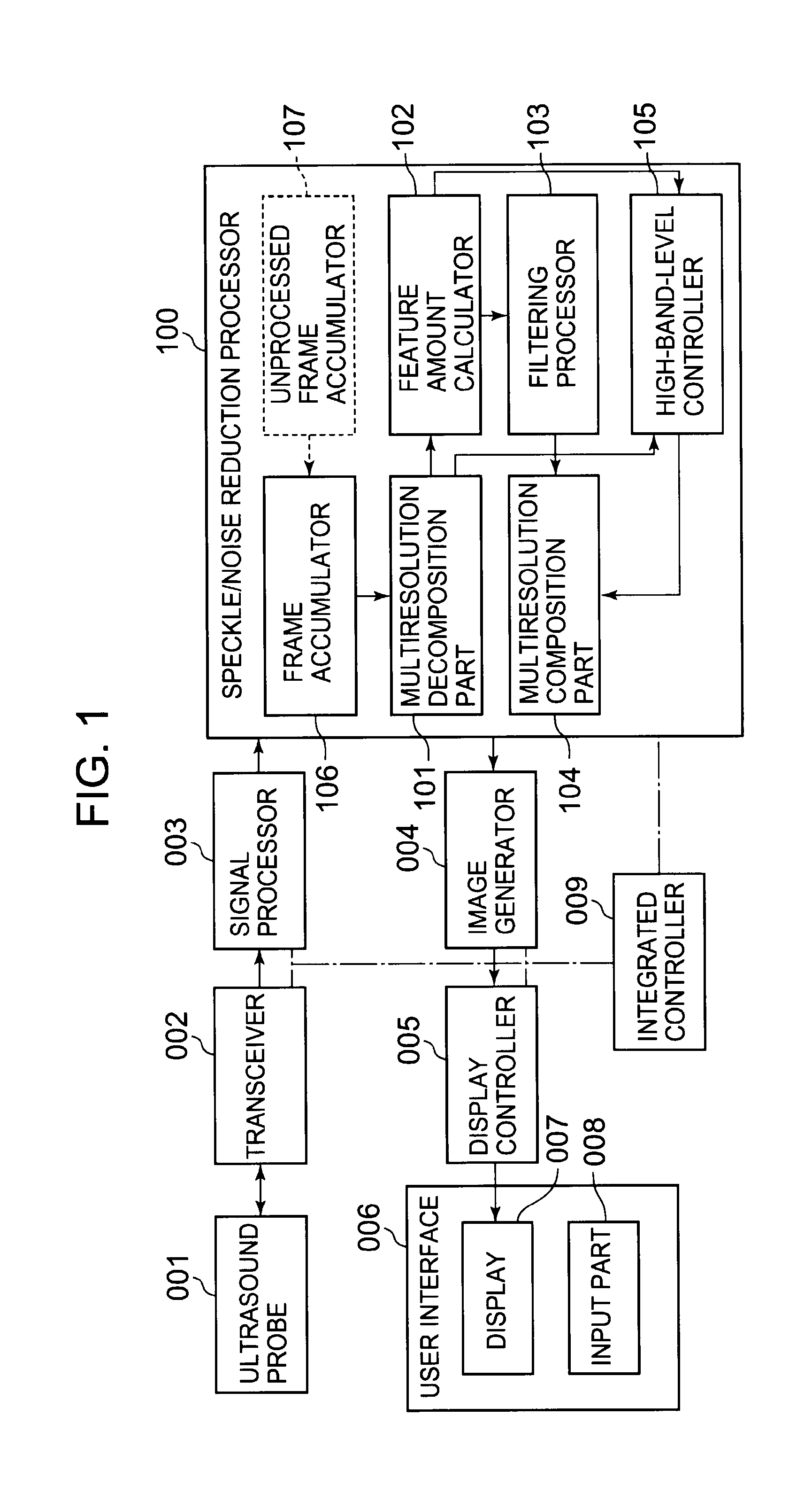
[0050]FIG. 1 is a block diagram showing the function of the ultrasound diagnosis apparatus according to this embodiment.

[0051]As shown in FIG. 1, the ultrasound diagnosis apparatus according to this embodiment has an ultrasound probe 001, a transceiver 002, a signal processor 003, an image generator 004, a speckle / noise reduction processor 100, a display controller 005, and a user interface 006. The user interface 006 has a display 007 such as a monitor, and an input part 008 such as a keyboard and a mouse.

[0052]The ultrasound probe 001 has a plurality of piezoelectric transducers. The ultrasound probe 001 converts pulse signals into ultrasound waves by using the piezoelectric transducers, and transmits the ultrasound waves obtained by the conversion to a subject. The pulse signals are inputted from the transceiver 002 described later.

[0053]Further, the ultrasound...

second embodiment

[0162]An ultrasound diagnosis apparatus according to a second embodiment of the present invention will be described below. The ultrasound diagnosis apparatus according to this embodiment is different in configuration from the first embodiment in that B-mode data after the speckle / noise reduction process is used to execute the speckle / noise reduction process on a next frame. The configuration of the ultrasound diagnosis apparatus according to this embodiment will be shown by the block diagram of FIG. 1. In the following description, function parts denoted by the same reference numerals as in the first embodiment have the same functions as far as there is no specific description.

[0163]FIG. 8 is a view for describing accumulation of B-mode data and a process using the accumulated B-mode data. In order to facilitate the description, FIG. 8 shows two dimensions of the spatial axis and temporal axis.

[0164]The frame accumulator 106 stores B-mode data inputted from the signal processor 003 ...

modification 1

(Modification 1)

[0168]Next, another example of the ultrasound diagnosis apparatus according to the present invention will be described. In this modification, unprocessed B-mode data are accumulated. At the time of execution of the speckle / noise reduction process, the latest unprocessed frame is outputted to the frame accumulator 106.

[0169]FIG. 9 is a view for describing accumulation of B-mode data and the process using the accumulated B-mode data in this modification.

[0170]FIG. 9 is expressed in two-dimensions of the spatial axis and the temporal axis.

[0171]The ultrasound diagnosis apparatus of this modification has a configuration that an unprocessed frame accumulator 107 shown by a dotted line is added to the ultrasound diagnosis apparatus according to the second embodiment.

[0172]The unprocessed frame accumulator 107 has a storing medium such as a memory and a hard disk.

[0173]The unprocessed frame accumulator 107 stores B-mode data inputted from the signal processor 003 sequential...


PUM


Abstract

An ultrasound diagnosis apparatus of the present invention has: an image generator configured to execute transmission/reception of ultrasound waves to chronologically generate ultrasound image data of plural frames; a multiresolution decomposition part configured to hierarchically perform multiresolution decomposition on the ultrasound image data to acquire first-order to nth-order (n represents a natural number of 2 or more) low-band decomposition image data and first-order to nth-order high-band decomposition image data; a feature amount calculator configured to calculate a feature amount based on the acquired low-band decomposition image data; a filtering processor configured to perform a filtering operation on the calculated feature amount; and a multiresolution composition part configured to execute multiresolution composition using the low-band decomposition image data and high-band decomposition image data to generate a composite image. Thus, the apparatus can efficiently reduce change in speckle/noise in the temporal direction and perform a process without a time phase delay.

Description

BACKGROUND OF THE INVENTION[0001]1. Field of the Invention[0002]The present invention relates to an ultrasound diagnosis apparatus that transmits ultrasound waves to a subject and obtains an ultrasound image based on the waves reflected from the subject.[0003]More specifically, the present invention relates to an ultrasound diagnosis apparatus that executes a correction process on a generated ultrasound image.[0004]2. Description of the Related Art[0005]An ultrasound diagnosis apparatus transmits, to a subject, ultrasound waves generated from transducers incorporated in an ultrasound probe. The ultrasound diagnosis apparatus receives, by the transducers, reflected waves from a subject tissue of the transmitted ultrasound waves, generates an ultrasound tomographic image of the subject from the received reflected waves, and displays the ultrasound tomographic image.[0006]Signals received from a plurality of subject tissues adjacent to each other interfere with each other because havin...

Claims


Application Information

Patent Timeline
Patent Type & Authority Applications(United States)
IPC IPC(8): A61B8/14
CPCA61B8/14G01S7/52077G06T5/002G06T5/10G06T2207/10072G06T2207/10076G06T2207/30004G06T2207/10136G06T2207/20016G06T2207/20064G06T2207/20182G06T2207/20192G06T2207/10132
Inventor OSUMI, RYOTA
Owner TOSHIBA MEDICAL SYST CORP
Why Eureka
Try Eureka