
Surgical resection apparatus

a surgical and resection technology, applied in the field of surgical resection apparatus, can solve the problems of most undesirable situation and tissue effect, and achieve the effects of reducing or preventing tissue ‘spitting’, high localised power level, and increasing power level

Active Publication Date: 2010-11-11
CREO MEDICAL LTD
View PDF27 Cites 45 Cited by
  • Summary
  • Abstract
  • Description
  • Claims
  • Application Information

AI Technical Summary

Benefits of technology

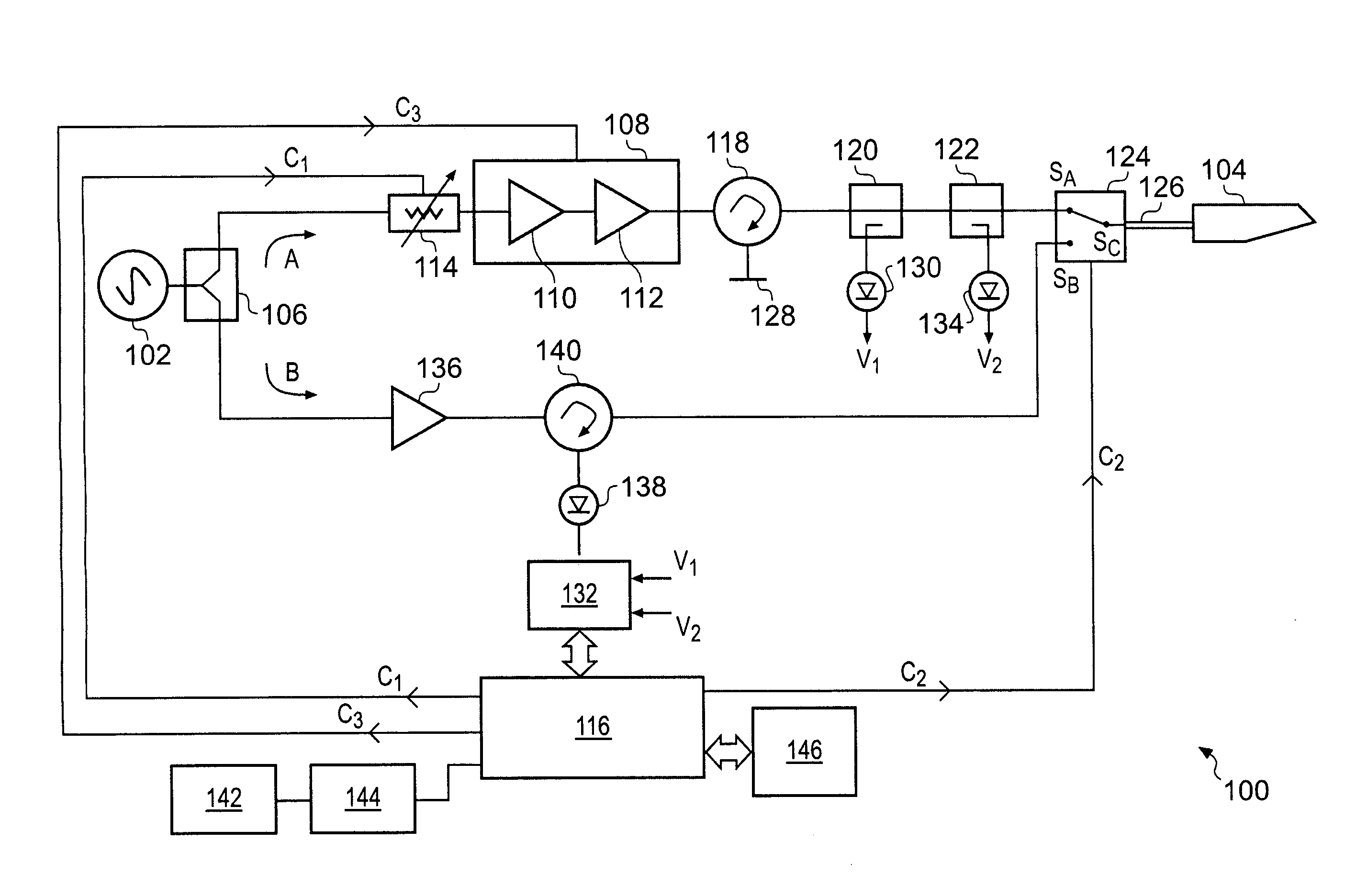
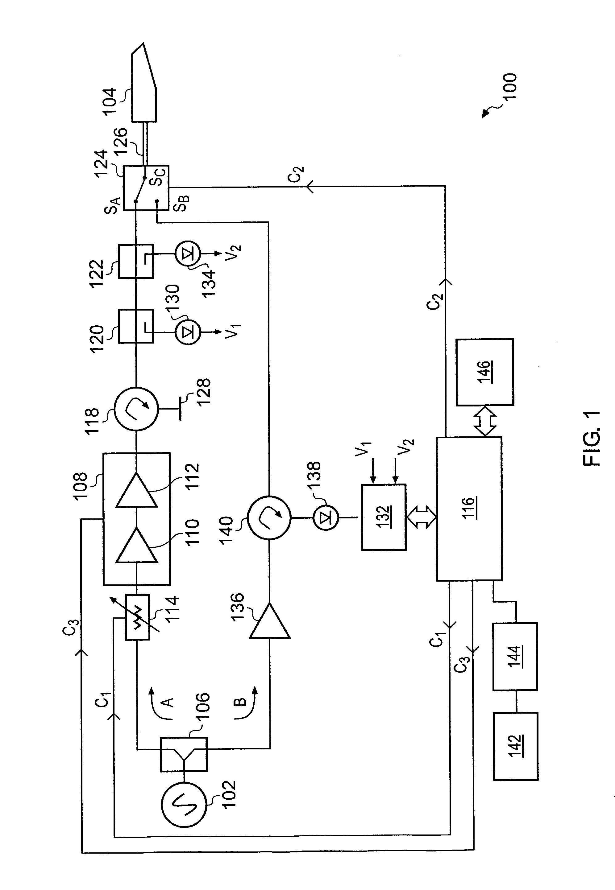
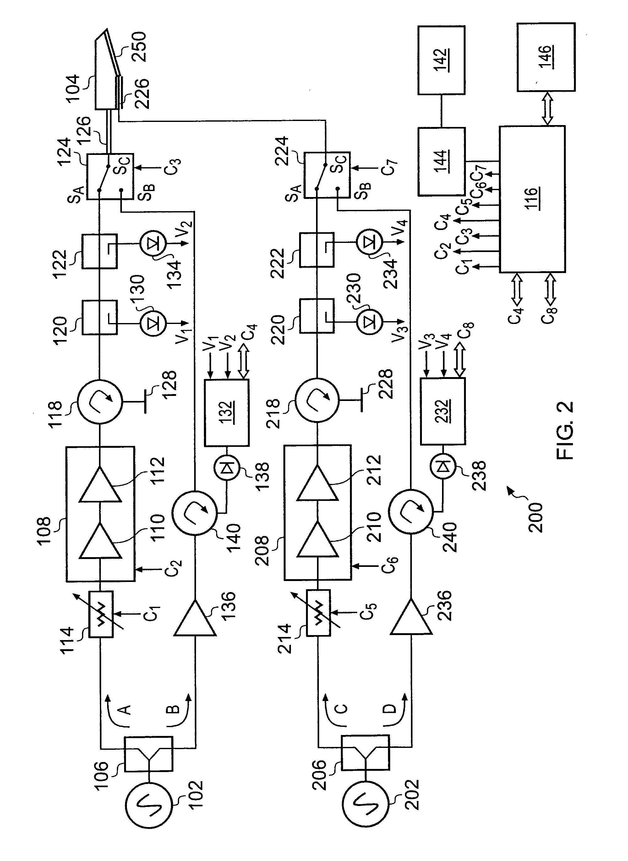
The patent describes a surgical apparatus that uses microwave energy to perform cutting and tissue ablation. The apparatus has a treatment channel and a measurement channel for microwave radiation, with the option of a third channel for low power measurement. The apparatus includes an antenna connected to a microwave source and a detector through a signal transfer unit. The detector can measure the reflected power levels and decide when to activate the higher power level for treatment. The apparatus can also include a circulator and carrier cancellation circuit for separating the forward and reflected signals. The impedance adjustor can detect the magnitude and phase of the reflected signal and adjust the impedance accordingly. The technical effects of the patent include improved safety and efficiency in the use of microwave energy in surgery.

Problems solved by technology

The power level required to achieve this may be sufficient to cause effects in the tissue, e.g. ablation or heating, which may be undesirable.
This situation is most undesirable.

Method used


Image

  • Surgical resection apparatus
  • Surgical resection apparatus
  • Surgical resection apparatus

Examples


first embodiment

[0148]FIG. 4 shows a surgical instrument 400 with two radiating structures. The surgical instrument 400 is a rectangular block of waveguide (i.e. dielectric) material whose end is formed into a scalpel shape, with upper and lower angled sharp edges 402, 404 meeting at a point 406. The lower angled edge 404 is longer than the upper angled edge and forms a main blade of the surgical instrument.

[0149]The block of waveguide is coupled directly to the transmission cable of the apparatus that carries microwave energy at a first (higher) frequency. Metallization 408 is provided on the surfaces of the block of waveguide except at a narrow region 410 adjacent to the main blade (i.e. around lower angled edge 404). The unmetallized region 410 therefore acts as an antenna (e.g. radiating blade) for the microwave energy at the first frequency.

[0150]A coaxial cable 412 is mounted along the bottom of the block of waveguide. This coaxial cable 412 is the transmission cable of the apparatus that car...

second embodiment

[0153]FIG. 5 shows a surgical instrument 500 capable of launching energy into tissue at two different microwave frequencies. Similarly to the instrument shown in FIG. 4, surgical instrument 500 comprises a block of waveguide 501 whose end is formed into a scalpel shape having upper and lower angled sharp edges 502, 504 which meet at a point 506. The lower angled edge 504 is longer and provides the main cutting blade of the instrument 500. A layer of metallization 508 is provided on the surfaces of the block of waveguide 501 except at a region 510 adjacent to the lower angled edge 504. Similarly to FIG. 4, the block of waveguide is coupled directly to the transmission cable (waveguide) 520 of the apparatus that carries microwave energy at the first (higher) frequency. The unmetallized region 510 therefore acts as an antenna (e.g. radiating blade) for the microwave energy at the first frequency.

[0154]In this embodiment, the entire layer of metallization 508 is used as a second antenna...

third embodiment

[0156]FIG. 6 shows a surgical instrument 600 capable of launching energy into tissue at two different microwave frequencies. Similarly to the instrument shown in FIG. 4, surgical instrument 600 comprises a block of waveguide 601 whose end is formed into a scalpel shape having upper and lower angled sharp edges 602, 604 which meet at a point 606. The lower angled edge 604 is longer and provides the main cutting blade of the instrument 600. A layer of metallization 608 is provided on the surfaces of the block of waveguide 601 except at a region 610 adjacent the lower angled edge 604. Similarly to FIG. 4, the block of waveguide is coupled directly to the transmission cable (not shown) of the apparatus that carries microwave energy at the first (higher) frequency. The unmetallized region 610 therefore acts as an antenna (e.g. radiating blade) for the microwave energy at the first frequency.

[0157]In this embodiment, a self-contained patch antenna 611 is mounted on layer of metallization ...


PUM


Abstract

Surgical cutting apparatus having a treatment channel and a measurement channel for conveying microwave energy from a source to an antenna at a cutting edge. The measurement channel operates at lower power than the treatment channel for determining when higher energy can be safely applied. The apparatus may deliver microwave radiation at differing frequencies to one or more antennas at the cutting edge, e.g. to provide different treatment effects. The source may generate an output for an antenna whose frequency can be selected e.g. for most efficient operation. Selection may be automatic based on detected magnitude and phase of reflected signals during a frequency sweep of a forward signal. Power delivered to tissue via the cutting element may be manually boosted to deal with large blood vessels. The apparatus may include a reflected power monitor for recognising behaviour in reflected signals received from the antenna to trigger automatic pre-emptive action.

Description

TECHNICAL FIELD[0001]This application relates to surgical resection apparatus which is arranged to controllably deliver microwave energy into biological tissue.BACKGROUND TO THE INVENTION[0002]The disclosure herein builds on the content of the applicant's earlier UK patent application no. 0620060.4, filed on 10 Oct. 2006. That document describes a surgical cutting e.g. resection apparatus comprising a source of microwave radiation that is coupled to a surgical instrument having an antenna associated with a blade for cutting biological tissue, wherein the antenna is arranged to controllably deliver microwave energy from the source to a region where the blade cuts through tissue. The microwave energy can coagulate blood to effectively seal off the blood flow at the cutting region. Such an effect may be particularly beneficial when performing surgery on highly vascularised organs such as the liver or spleen.[0003]The use of high microwave frequencies (e.g. 10 GHz or higher) offers part...

Claims


Application Information

Patent Timeline
Patent Type & Authority Applications(United States)
IPC IPC(8): A61B18/18A61B17/32
CPCA61B18/18A61B18/1815A61B2018/1876A61B2018/183A61B17/3211A61B2018/00642A61B2018/00648A61B2018/00708A61B2018/00732A61B2018/00755A61B2018/00785A61B2018/1823
Inventor HANCOCK, CHRISTOPHER PAUL
Owner CREO MEDICAL LTD
Learn More