Systems and Methods for Logic Verification

a logic verification and logic technology, applied in the field of logic verification systems and methods, can solve the problems of inability to scale up, become extremely expensive, and take a long time to synthesize the process, and achieve the effect of avoiding inefficiency, avoiding inefficiency, and avoiding inefficiency

Active Publication Date: 2010-11-11
ET INT
View PDF8 Cites 46 Cited by
  • Summary
  • Abstract
  • Description
  • Claims
  • Application Information

AI Technical Summary

Problems solved by technology

This approach is not scalable and becomes extremely expensive as the complexity of the target logic increases.
Also, the synthesizing processes normally takes a long time, which makes this approach very inefficient at the early stages of the chip logic development when design changes occur very often.
Furthermore, FPGAs are intrinsically much slower than custom designed circuits.
The biggest problem of simulating complex chip logic on a PC cluster is the low performance.
The main hindering factors come from instruction and data cache locality that are not well-suited to this type of simulation, inefficient communication channels, and operating system overhead.
Those systems are usually extremely expensive to develop and upgrade, and tend to be less flexible than other types of systems.
The existing machines are generally not commercially available to outside users.

Method used


Image

  • Systems and Methods for Logic Verification
  • Systems and Methods for Logic Verification
  • Systems and Methods for Logic Verification

Examples


Embodiment Construction

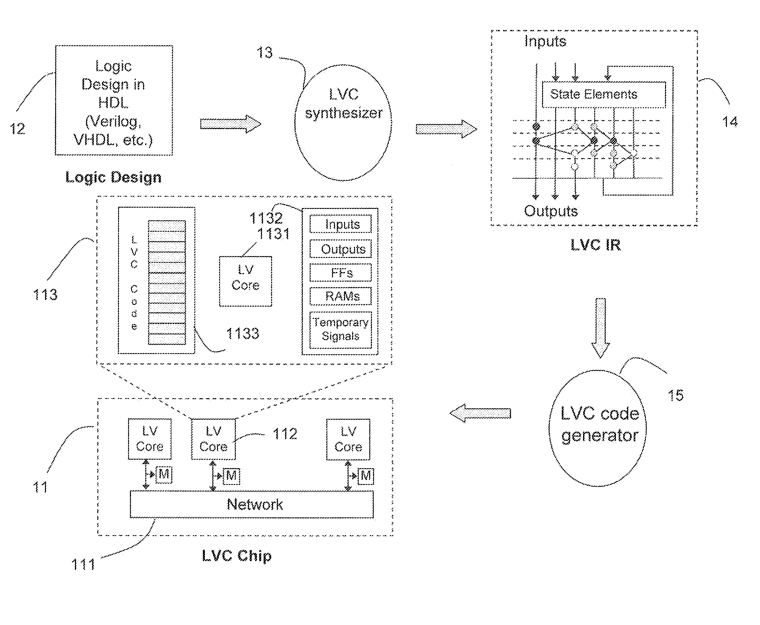
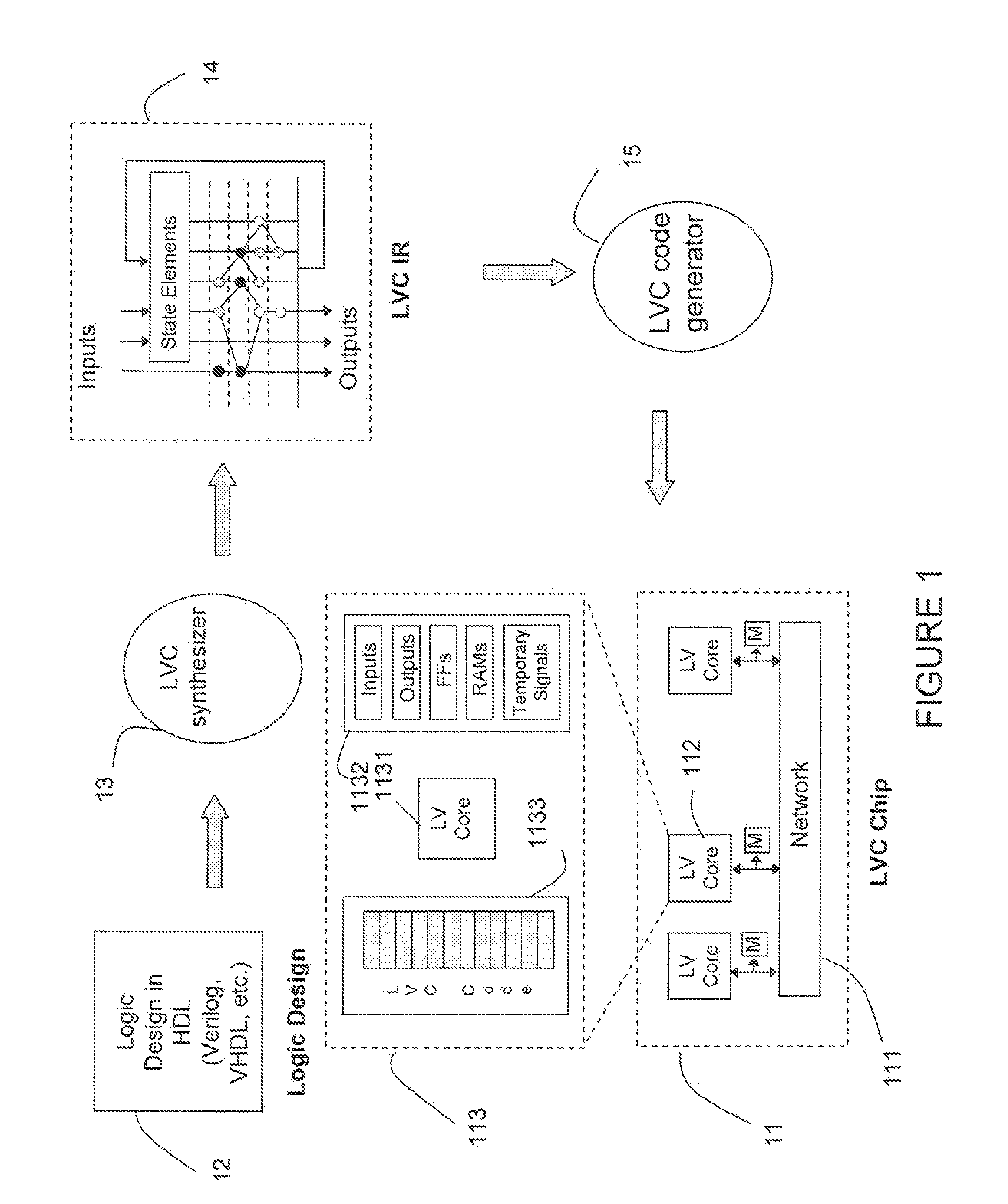
[0017]FIG. 1 shows a conceptual block / flow diagram that may be used to describe various embodiments of the invention. Embodiments of the invention may include a logic verification core (LVC) chip 11. LVC chip may include a number of LVCs 112, each of which may have an associated memory M, and which may be interconnected by means of a network 111. The associated memory M may be an individual memory component for each LVC 112, or the associated memory may comprise a portion of a larger memory component that may be shared among multiple LVCs 112.

[0018]An LVC 112 may comprise a logic verification core processor 1131 (which may be referred to below as “LP”), and may include local data memory to hold various associated components 1132, such as input, output, etc. The logic verification core processor may also include local instruction memory 1133 for the LVC to access for execution.

[0019]Under traditional event-driven simulation (e.g., CSim), events may be generated when logic cells (netl...


PUM


Abstract

Methods and systems for simulating logic may translate logic design into executable code for a multi-processor based parallel logic simulation device. A system may implement one or more parallel execution methods, which may include IPMD, MPMD, and / or DDMT.

Description

CROSS-REFERENCE TO RELATED APPLICATION[0001]This application is a divisional application of U.S. patent application Ser. No. 11 / 937,577, filed Nov. 9, 2007, which claims the priority of U.S. Provisional Patent Application No. 60 / 866,517, filed on Nov. 20, 2006, both of which are incorporated herein by reference.FIELD OF ENDEAVOR[0002]Embodiments of the invention are may address multi-core chip architectures that may be used for logic verification and associated methods for using such architectures.BACKGROUND OF THE INVENTION[0003]Existing logic verification technology is mostly based on the use of field-programmable gate arrays (FPGAs), a cluster of computers (e.g., PCs), or specially designed application-specific integrated circuit (ASIC) systems.[0004]Current FPGA-based technologies usually try to directly map the target logic into a group of FPGAs and to emulate the target system. This approach is not scalable and becomes extremely expensive as the complexity of the target logic ...

Claims


Application Information

Patent Timeline
Patent Type & Authority Applications(United States)
IPC IPC(8): G06F17/50
CPCG06F17/5022G06F30/33
Inventor GAO, GUANG R.CHEN, FEI
Owner ET INT
Why Eureka
Try Eureka