Beverage brewing unit

a technology for brewing units and beverages, applied in beverage vessels, household appliances, kitchen equipment, etc., can solve the problems of complex devices, affecting the extraction conditions, and not suitable for low-cost and therefore entry-level use, and achieves less moving parts, less need for tubing, and direct fluid connection

Active Publication Date: 2010-11-18
SOC DES PROD NESTLE SA
View PDF78 Cites 61 Cited by
  • Summary
  • Abstract
  • Description
  • Claims
  • Application Information

AI Technical Summary

Benefits of technology

[0012]The present invention also relates to a brewing unit for an easy insertion of a capsule but of simpler conception, in particular, that requires fewer moving parts, a more direct fluid connection with less need for tubings, a more compact design, a more user-friendly closure actuation and / or which prevents hot water projections when opened upon brewing.

Problems solved by technology

One problem encountered is the positioning of the capsule in the device and the closing of the latter around the capsule to perform the brewing process.
Bad positioning may damage the capsule, and thus affect the conditions of extraction.
However, these devices are complex to produce and are not suitable for low-cost and therefore entry-level coffee machines for the consumer market.
The disadvantage of this device is that it comprises two movable parts for the extraction, which makes the mechanical principle more complicated.
This arrangement involves several problems.
The pod must be moved during the closure of the brewing chamber and this can cause blocking and it also makes the retaining means of the pod more complex.
Moreover, opening and closing the brewing chamber involves simultaneously a linear displacement of the movable rear part within the housing, of the movable front part within the housing and of the outlet duct through the housing which increases the risk of hyper-guiding and jamming or improper alignment of the various parts that linearly move one relative to another.
The fluid system comprises a moving assembly which makes the fluid system more complex to assemble.
Furthermore, an unoccupied volume is left within the machine between the front member and the casing when the outlet duct is in its retracted position.

Method used


Image

  • Beverage brewing unit
  • Beverage brewing unit
  • Beverage brewing unit

Examples


first embodiment

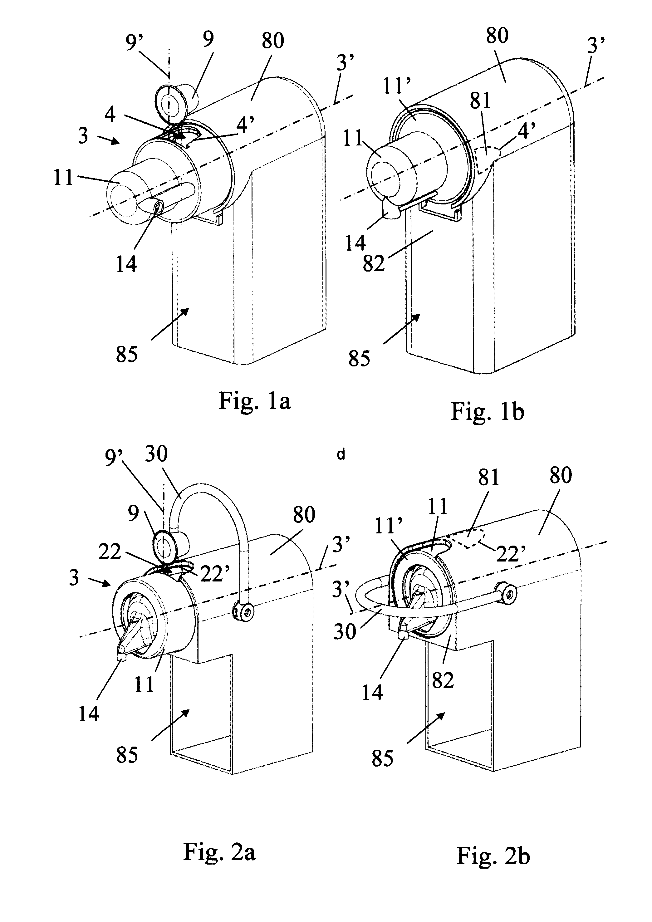
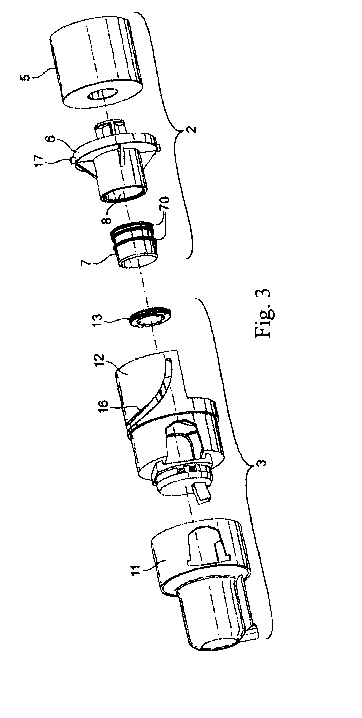
[0029]the invention is now described in relation to FIGS. 1a, 1b and 3 to 6.

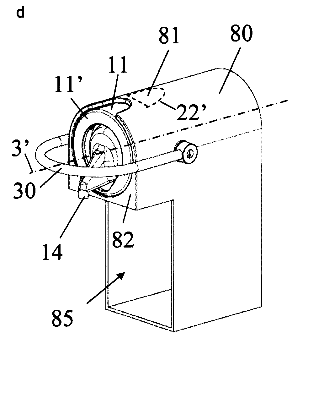
[0030]FIGS. 1a and 1b show a beverage machine with a main casing 80 and a brewing unit 1 having a helicoidal closure mechanism along a straight line, details of brewing unit 1 being illustrated in FIGS. 3 to 6.

[0031]Brewing unit 1 comprises a capsule holding assembly with a beverage outlet 14 forming a first movable assembly 3 and a water injection assembly with a water inlet or line 25 in casing 80 forming a second fixed assembly 2. Each assembly 2, 3 delimits at least part of a brewing chamber 7′ for containing an ingredient capsule 9.

[0032]In a variation, the capsule injection assembly may be movable and the capsule holding assembly may be fixed or movable.

[0033]Holding assembly 3 has a tubular cover 11 and is movable away from the cooperating injection assembly 2 into an open position within the beverage machine for forming between assemblies 2, 3 a passage 4 for inserting into and / or removing from the b...


PUM


Abstract

A beverage machine having a beverage brewing unit for receiving a single-serve capsule and including a capsule holding assembly for holding a capsule in a position during insertion by gravity of the capsule in the brewing unit; and a water injection assembly for at least partially enclosing the capsule and providing water in the capsule. The capsule holding part forms a front part of the unit and is mounted to the capsule injection assembly in a manner to be displaceable along a substantially horizontal path whereas the water injection assembly is located in a rear fixed part of the unit. The beverage machine has an outermost casing. One of these brewing unit assemblies can be moved or telescoped out or through this casing for inserting/removing the ingredient capsule and retracted into the outermost casing for bringing the brewing unit into its capsule extraction configuration.

Description

FIELD OF THE INVENTION[0001]The present invention relates to a beverage brewing unit using capsules that contain a food ingredient for preparing a beverage or like food. The brewing unit is of simpler conception and of lower cost compared to existing brewing units.BACKGROUND ART[0002]One problem encountered is the positioning of the capsule in the device and the closing of the latter around the capsule to perform the brewing process. The capsule usually has to be positioned by the user on a capsule support or in a housing, then the device is closed manually or automatically around the capsule.[0003]It is important to correctly position the capsule so that the device closes correctly around the latter and a good seal is thus achieved to ensure good conditions of extraction. Bad positioning may damage the capsule, and thus affect the conditions of extraction. The loading of the capsule must also be easy, without trial and error as to the correct position of the capsule in the device. ...

Claims


Application Information

Patent Timeline
Patent Type & Authority Applications(United States)
IPC IPC(8): A47J31/44
CPCA47J31/3633A47J31/407A47J31/3628A47J31/369
Inventor GAVILLET, GILLESMORI, PETERMOSER, RENZOKOLLEP, ALEXANDRE
Owner SOC DES PROD NESTLE SA
Why Eureka
Try Eureka