Electric submersible pumping system for dewatering gas wells

Inactive Publication Date: 2010-11-18
SCHLUMBERGER TECH BV
View PDF28 Cites 55 Cited by
  • Summary
  • Abstract
  • Description
  • Claims
  • Application Information

AI Technical Summary

Benefits of technology

[0006]In another embodiment, a pumping system includes a submersible high speed electric motor operable to rotate a drive shaft; a high speed pump rotationally fixed to the drive shaft; an isolation device operable to expand into engagement with a tubular string, thereby fluidly isolating an inlet of the pump from an outlet of the pump and ro

Problems solved by technology

As natural gas wells mature, many experience a decrease in production due to water build up in the annulus creating back pressure on the reservoir.
The gas industry hav

Method used


Image

  • Electric submersible pumping system for dewatering gas wells
  • Electric submersible pumping system for dewatering gas wells
  • Electric submersible pumping system for dewatering gas wells

Examples


Embodiment Construction

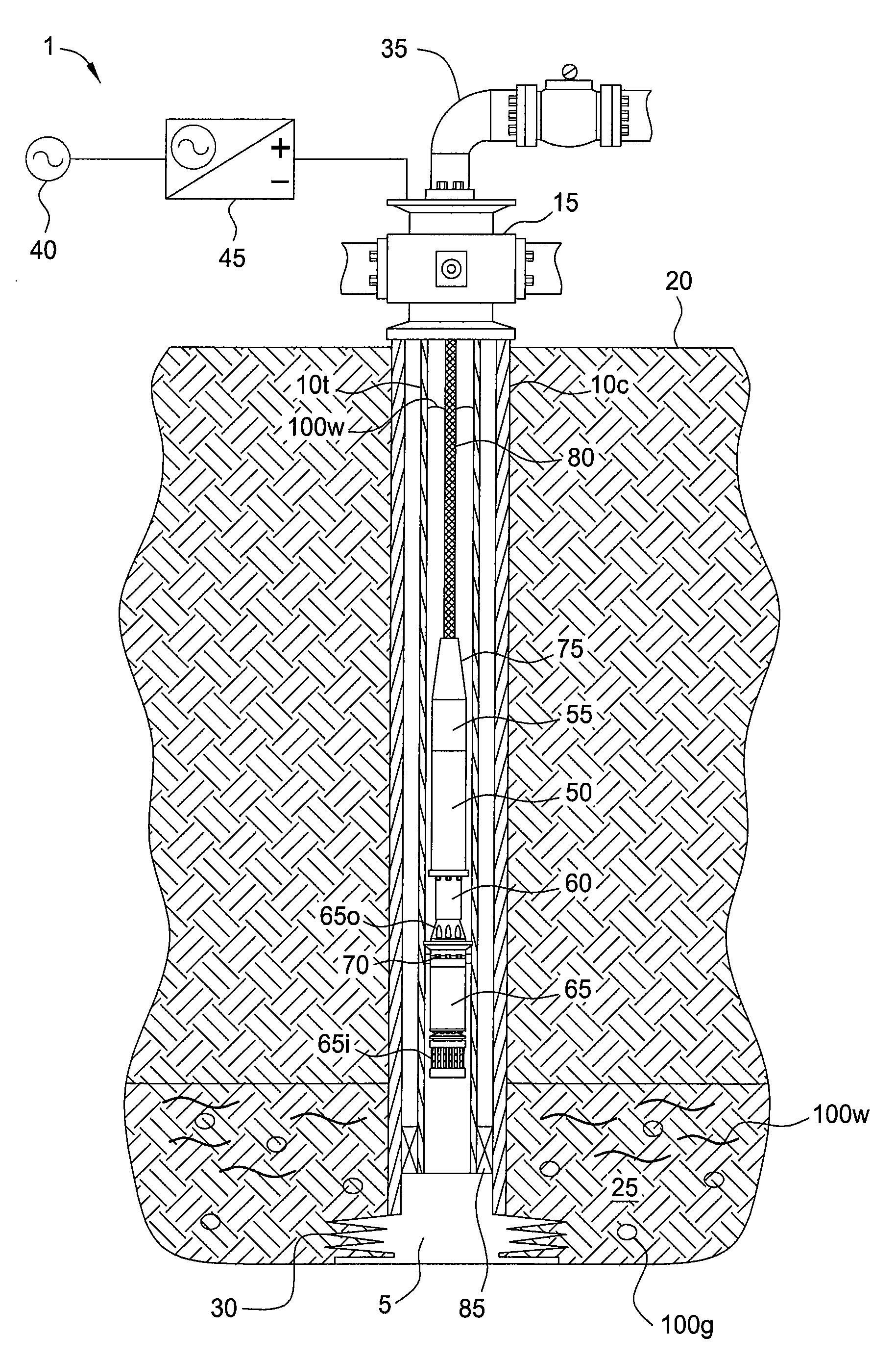
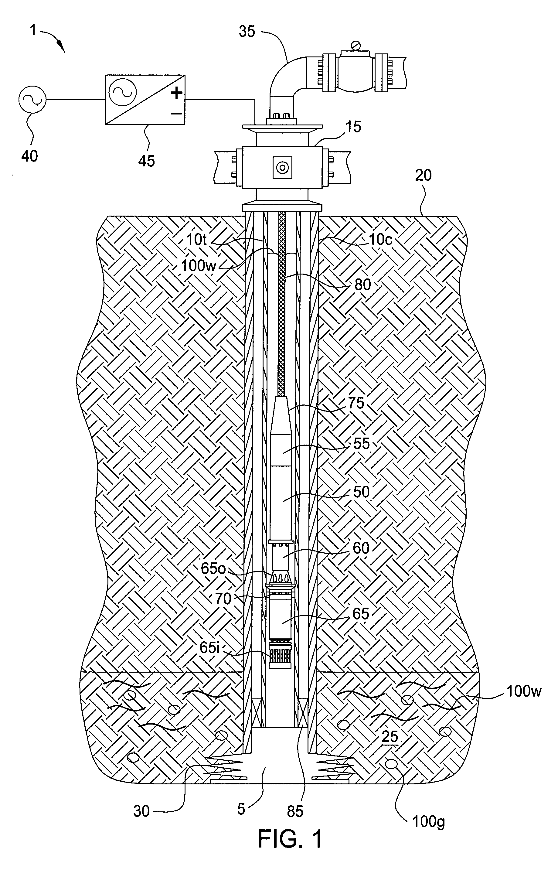
[0011]FIG. 1 illustrates a pumping system 1 deployed in a wellbore 5, according to one embodiment of the present invention. The wellbore 5 has been drilled from a surface of the earth 20 or floor of the sea (not shown) into a hydrocarbon-bearing (i.e., natural gas 100g) reservoir 25. A string of casing 10c has been run into the wellbore 5 and set therein with cement (not shown). The casing 10c has been perforated 30 to provide to provide fluid communication between the reservoir 25 and a bore of the casing 10. A wellhead 15 has been mounted on an end of the casing string 10c. An outlet line 35 extends from the wellhead 15 to production equipment (not shown), such as a separator. A production tubing string 10t has been run into the wellbore 5 and hung from the wellhead 15. A production packer 85 has been set to isolate an annulus between the tubing 10t and the casing 10c from the reservoir 25. The reservoir 25 may be self-producing until a pressure of the gas 100g is no longer suffic...


PUM


Abstract

Embodiments of the present invention generally relate to an electric submersible pumping system for dewatering gas wells. In one embodiment, a method of unloading liquid from a reservoir includes deploying a pumping system into a wellbore to a location proximate the reservoir using a cable. The pumping system includes a motor, an isolation device, and a pump. The method further includes setting the isolation device, thereby rotationally fixing the pumping system to a tubular string disposed in the wellbore and isolating an inlet of the pump from an outlet of the pump; supplying a power signal from the surface to the motor via the cable, thereby operating the pump and lowering a liquid level in the tubular string to a level proximate the reservoir; unsetting the isolation device; and removing the pump assembly from the wellbore using the cable.

Description

BACKGROUND OF THE INVENTION[0001]1. Field of the Invention[0002]Embodiments of the present invention generally relate to an electric submersible pumping system for dewatering gas wells.[0003]2. Description of the Related Art[0004]As natural gas wells mature, many experience a decrease in production due to water build up in the annulus creating back pressure on the reservoir. The gas industry have utilized varying technologies to alleviate this problem, however most do not meet the economic hurdle as they require intervention such as pulling the tubing string.SUMMARY OF THE INVENTION[0005]Embodiments of the present invention generally relate to an electric submersible pumping system for dewatering gas wells. In one embodiment, a method of unloading liquid from a reservoir includes deploying a pumping system into a wellbore to a location proximate the reservoir using a cable. The pumping system includes a motor, an isolation device, and a pump. The method further includes setting the ...

Claims


Application Information

Patent Timeline
IPC IPC(8): E21B37/00E21B21/00E21B43/00F04B35/04
CPCE21B43/128F04B17/03F04B43/04E21B43/13
Inventor FIELDER, LANCE I.WORRALL, ROBERT NICHOLAS
Owner SCHLUMBERGER TECH BV
Why Eureka
Try Eureka