Ice Drill

a drill and ice technology, applied in the field of ice drills, can solve the problems of considerable cost saving and the like, and achieve the effect of broadening the field of use of ice drills

Inactive Publication Date: 2010-11-18
MORA OF SWEDEN
View PDF19 Cites 5 Cited by
  • Summary
  • Abstract
  • Description
  • Claims
  • Application Information

AI Technical Summary

Benefits of technology

[0008]The object of the present invention is to provide a device of the type defined in the introduction, which enables a broadened field of use of ice drills equipped with such a device.

Problems solved by technology

Furthermore, it involves a considerable saving of costs to be able to convert an ice drill from hand operation to motor operation instead of having a separate ice drill for each type of operation.

Method used


Image

  • Ice Drill
  • Ice Drill
  • Ice Drill

Examples


Embodiment Construction

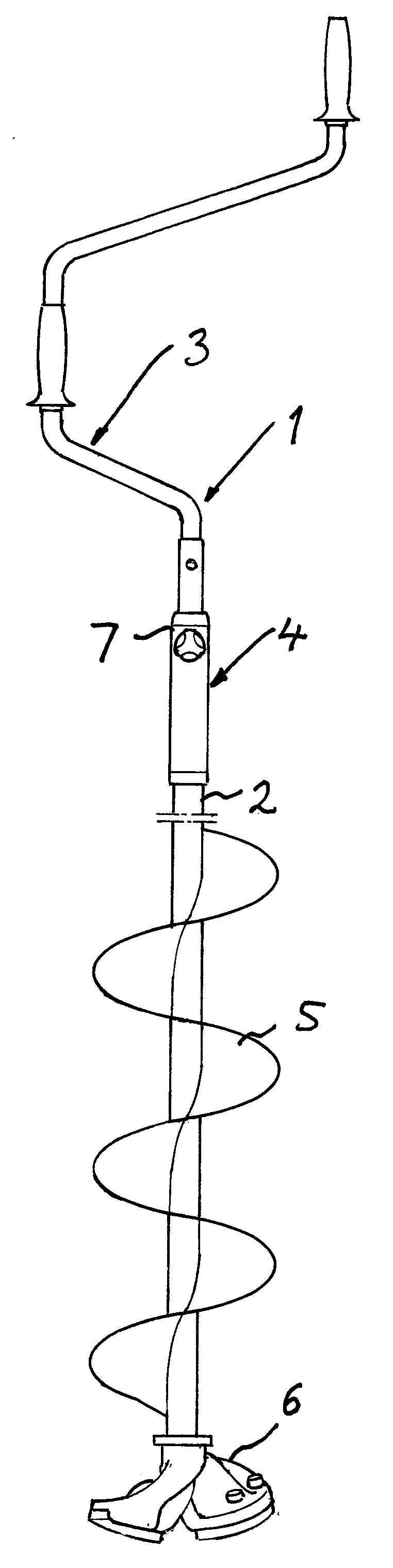
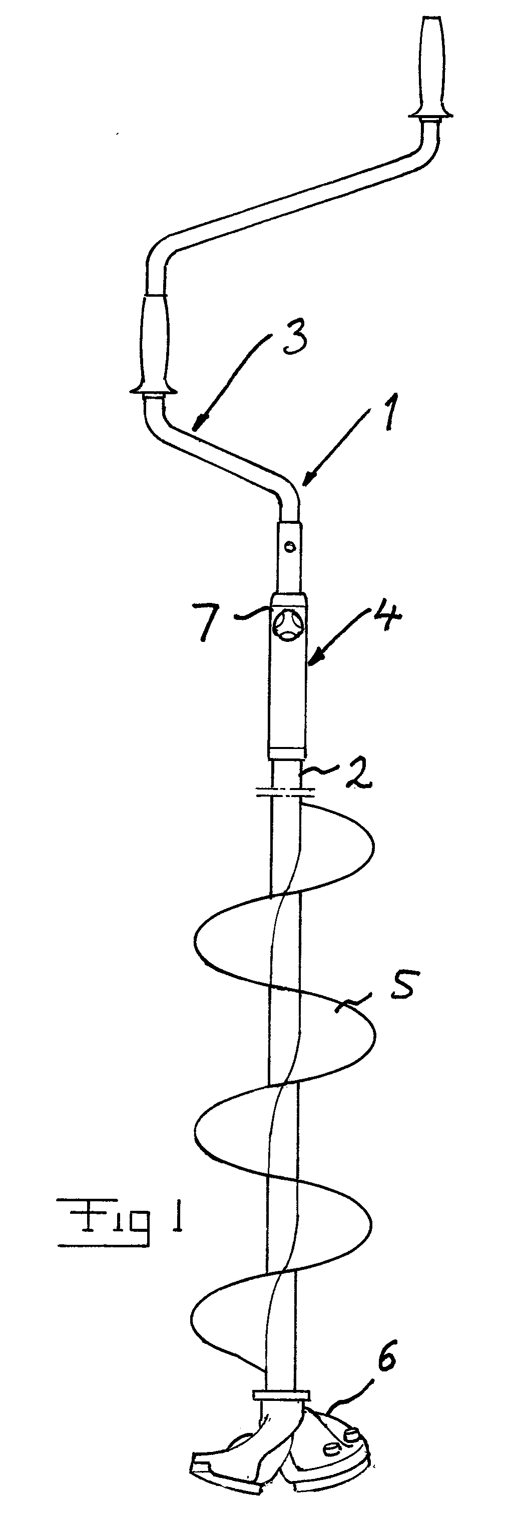
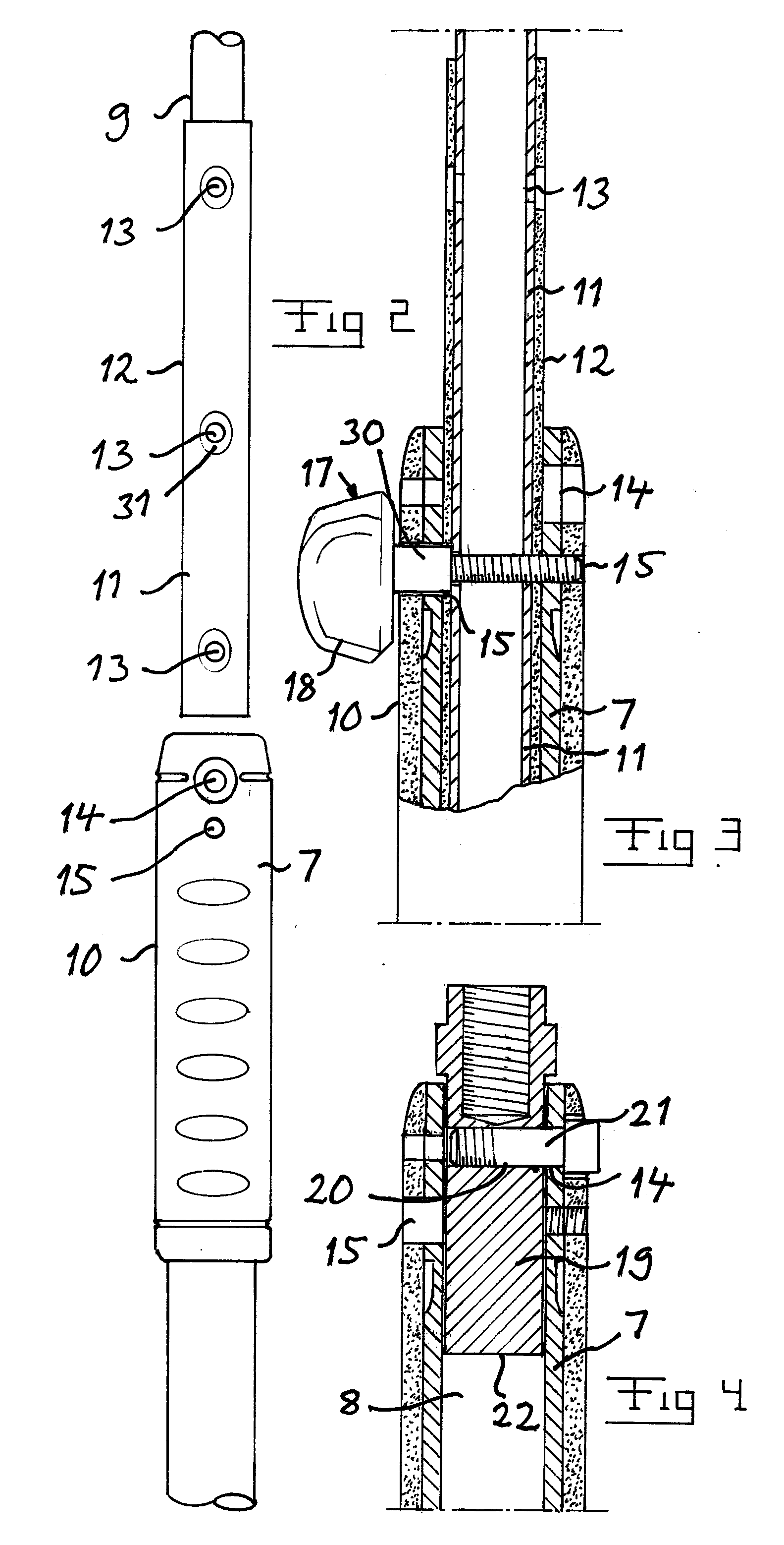
[0030]An ice drill 1 according to an embodiment of the present invention is illustrated in FIG. 1. This has a central rigid drill rod 2, which for example is made of stainless steel or surface treated steel. A crank 3 is removably secured to the upper part of the drill rod through a device 4 according to the invention for making it possible to by hand power drive the drill rod 2 to rotate around the axis thereof for drilling. A spiral 5 extends around the drill rod from the region of a bore crown 6 and upwards for lifting crushed ice formed by drilling. The device 4 for connecting the crank 3 with the drill rod 2 constitutes the very core of the invention and will now be described while simultaneously referring to FIGS. 2-4. The drill rod end 7 is hollow and has an inner cavity 8 with a larger diameter than the outer diameter of the crank rod 9 itself. The drill rod end 7 is provided with a handle arranged externally thereof for providing a hand grip when releasing or loosening and ...


PUM


Abstract

A device is designed for optionally connecting a crank (3) and a motor shaft with a drill rod (2) of a tool for drilling holes through thick outdoor ice, on lakes and the like, by rotating the drill rod, for converting the tool between a tool for hand driven and a tool for motor driven drilling. The device has for this sake locking members for locking the crank and the motor shaft, respectively, to the drill rod, which are releasably arranged for removing the crank and the motor shaft, respectively, from the drill rod.

Description

FIELD OF THE INVENTION AND PRIOR ART[0001]The present invention relates to a device for connecting a crank with the drill rod of a tool for drilling holes through thick outdoor ice, on lakes and the like, by driving the crank by hand, which comprises means for establishing a connection of mutual insertion of a shaft of said crank and an end of the drill rod as well as a first member for interlocking them in this position.[0002]It is then theoretically possible that in such a connection the drill rod is intended to be inserted into and received in said crank shaft, but the circumstances are normally the opposite, inter alia depending upon that it is often from a grip point of view desired to have a smaller diameter of a rod forming said crank than of the drill rod. A device of this type is applicable to tools normally called ice drills, which is the reason for using this expression hereinafter.[0003]Outdoor ice means here ice on lakes, rivers, oceans and the like, where a flowing wat...

Claims


Application Information

Patent Timeline
Patent Type & Authority Applications(United States)
IPC IPC(8): F25C5/04
CPCA01K97/01F25C5/04E21B11/005E21B7/008E21B17/046E21B17/22A01K97/00E21B11/00B25F3/00
Inventor NORLING, TORE
Owner MORA OF SWEDEN
Why Eureka
Try Eureka