
Wheel for vehicle

a technology for vehicles and wheels, applied in the direction of disc wheels, vehicle components, transportation and packaging, etc., can solve the problems of inefficient welding of the disk flange, no improvement in wheel strength, etc., to reduce poor welding, improve welding efficiency, and improve the design characteristics of the wheel

Active Publication Date: 2010-11-18
TOPY INDUSTRIES
View PDF16 Cites 20 Cited by
  • Summary
  • Abstract
  • Description
  • Claims
  • Application Information

AI Technical Summary

Benefits of technology

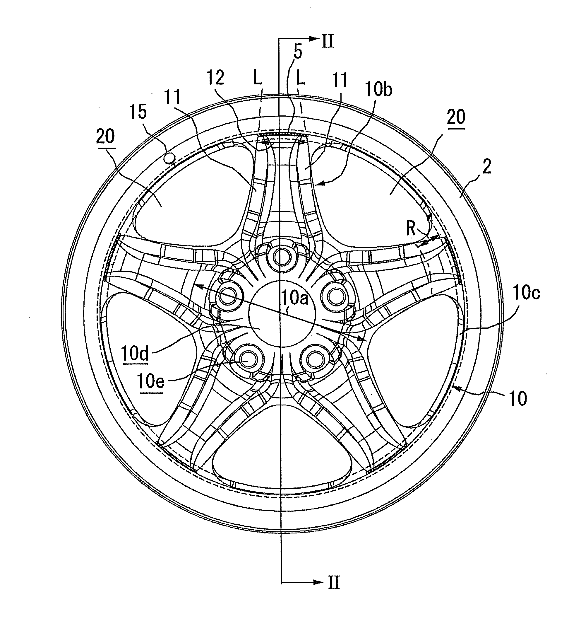
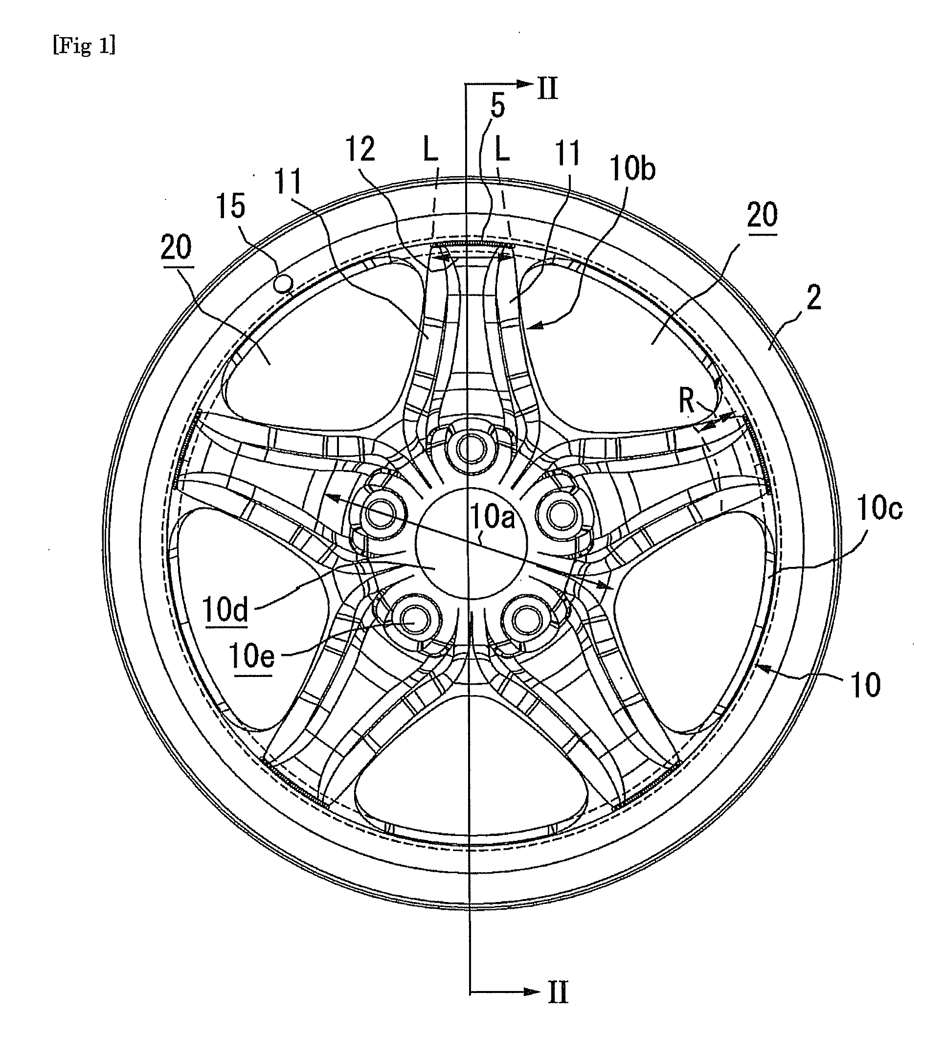
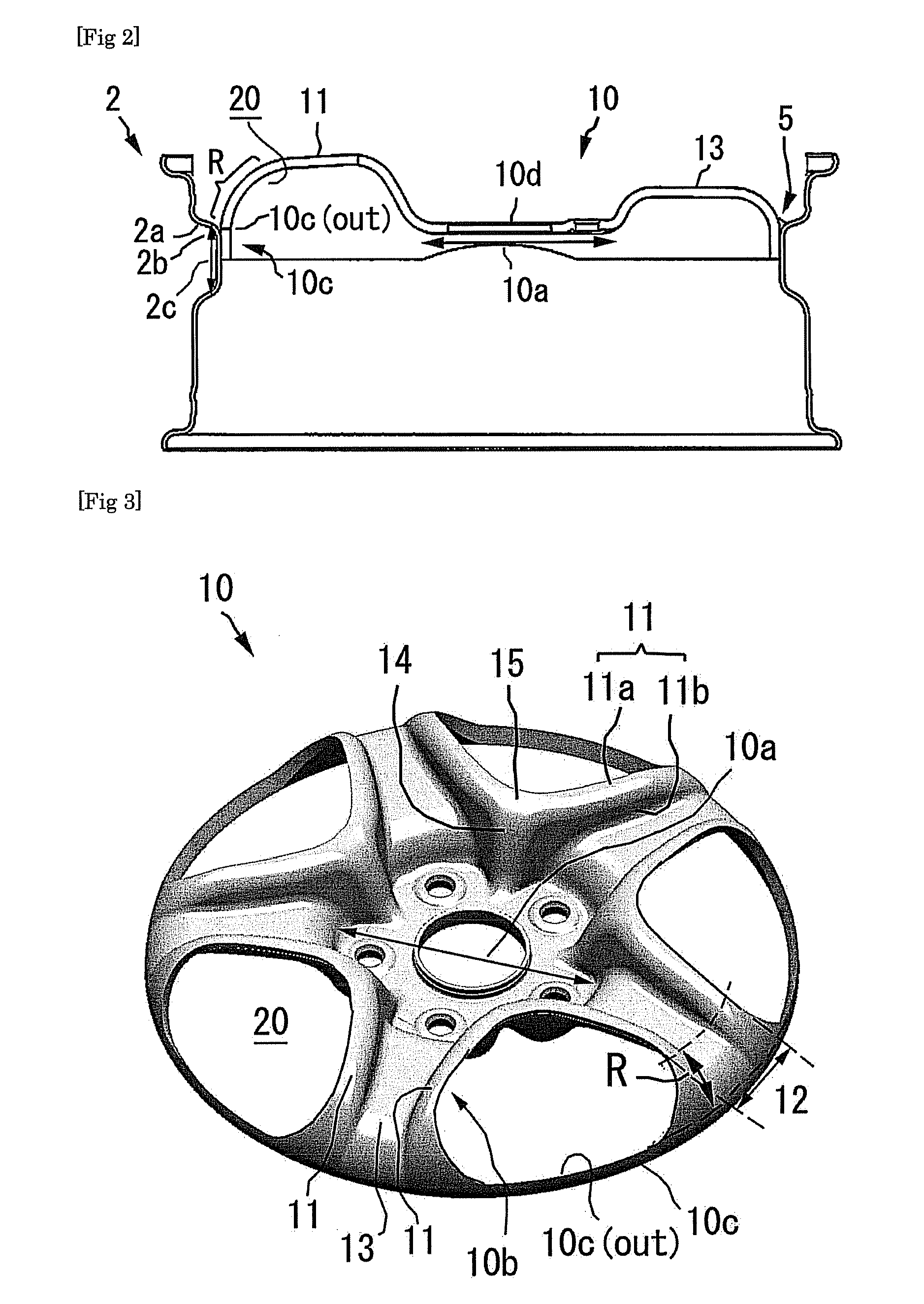
[0012]By this, since the curved-surface connecting portion positioned at an extending portion of the spoke has a larger material width and thus has higher strength, an end edge of this portion is less likely to undulate due to the bending. Thus, by welding the fitting surface facing the distal end of the spoke corresponding to this position, poor welding is reduced while ensuring reliable welding. And a force is transmitted from the rim to the hub mainly through the spokes. When a part of the disk flange adjacent to the decorative holes has a small material width, the force is hardly transmitted through this part of the disk flange. Therefore it is inefficient to weld that part of the disk flange, as substantially no improvement in wheel strength will result. Hence, by welding the fitting surface facing the distal end of the spoke, the efficiency of the welding and the productivity are improved.
[0014]A force is transmitted normally from the rim to the hub via the rim, the welded part, the disk flange, the spokes, and the hub mounting portion in the described order. Therefore, in the case that the spokes are too rigid, by welding the disk flange except a part that faces the distal end of the spoke, a less-rigid part of the disk flange than the distal end of the spoke can be welded. As a result, the stress concentration is relaxed, and thus fatigue endurance of the welded part and its adjacent area is improved.
[0016]In this embodiment, the outer shape of the disk becomes smaller and lighter-weight, compared to the case of fitting the outer circumferential surface of the disk flange into an inner circumferential surface of a bead seat of the rim. Also, the disk flange is easily prevented from interfering with a valve hole.
[0019]In this embodiment, the welded part is difficult to see externally and the appearance of the wheel is improved.
[0021]In this embodiment, the disk flange is retracted inside in the wheel axial direction relative to the rim. The outside end edge of the disk flange is difficult to see externally. Thus, the spokes look as if they connect directly to the rim and the design characteristics of the wheel is improved.
[0022]The present invention provides a wheel for vehicle including: a rim; and a disk that has integrally-formed spokes and large decorative holes and that is welded to the rim, wherein the wheel for vehicle is manufactured with improved productivity, reduction of poor welding, and sufficient joint strength.

Problems solved by technology

Therefore it is inefficient to weld that part of the disk flange, as substantially no improvement in wheel strength will result.

Method used


Image

  • Wheel for vehicle
  • Wheel for vehicle
  • Wheel for vehicle

Examples


Embodiment Construction

[0034]Embodiments of the present invention will be described below. In the following description, a steel wheel is applied as an example. However, the present invention covers not only the steel wheel, but also other material (for example, titanium and titanium alloy) wheels, as long as a disk is formed from a circular plate blank by bending an outer periphery of the blank by drawing or the like to form a disk flange.

[0035]In contrast, aluminum, magnesium, and other materials have lower material strength than the steel. Thus, casting is generally used for such aluminum, magnesium or other material to be integrally formed into a thick disk. For this approach, the structure for welding the disk and the rim together is not a problem. The present invention therefore does not cover the above thick disk that is integrally formed by casting (forging).

[0036]Preferably, the wheel of the present invention meets the official standard for fatigue strength. However, the present invention may als...


PUM


Abstract

A wheel for vehicle comprising: a rim 2 having a drop portion; and a disk 10 formed integrally from a plate material, the rim and the disk being welded together, wherein the disk has: a hub mounting portion 10a; a plurality of spokes 10b radially extending from the hub mounting portion toward an outer periphery of the disk; and a ring-shaped disk flange 10c that is connected to the spokes through a curved-surface connecting portion R that is formed by bending the spokes at an outer circumferential end thereof in a wheel axial direction, the disk flange extends in the wheel axial direction, and a decorative hole 20 is defined by the adjacent spokes, the hub mounting portion, and the disk flange, and a part that faces a distal end 12 of the spoke in a fitting area between an inner circumferential surface of the rim and an outer circumferential surface of the disk flange is welded.

Description

FIELD OF THE INVENTION[0001]The present invention relates to a wheel for vehicle such as automobiles, agricultural vehicles, and industrial vehicles.DESCRIPTION OF THE RELATED ART[0002]Cheap and low-cost steel wheels have been widely used. However, these steel wheels have a problem with their poor design, compared to aluminum wheels. Thus, in recent years, steel wheels having thin spokes and large decorative holes have been developed to provide a similar appearance to aluminum wheels. (See Patent Documents 1 to 3).[0003]According to the description in the Patent Document 1, a stamped disk is welded to a rim. The stamped disk has spokes formed integrally with a ring portion extending along the entire circumference of the stamped disk. A notch is provided on the ring portion, such that the notch does not interfere with an air stem (valve hole) on the rim when the ring portion is seated on a shoulder portion of the rim to be welded together.[0004]According to the description in the Pat...

Claims


Application Information

Patent Timeline
Patent Type & Authority Applications(United States)
IPC IPC(8): B60B3/10B60B3/04
CPCB60B3/002B60B3/10B60B3/044B60B3/007
Inventor SANO, TETSUSAKASHITA, YOSHINOBUTAKAGI, KEIITO, KIKUYA
Owner TOPY INDUSTRIES
Learn More