Closed loop negative feedback system with low frequency modulated gain

a negative feedback and closed loop technology, applied in the field of closed loop negative feedback systems with low frequency modulated gain, can solve the problems of increasing the production of high harmonics or electromagnetic interference (emi), increasing the size of magnetic components in the power supply, increasing the weight, size and cost of the power supply, etc., to reduce the harmonic distribution and reduce the harmonic distribution

Active Publication Date: 2010-11-18
FLEXTRONICS AP LLC
View PDF99 Cites 63 Cited by
  • Summary
  • Abstract
  • Description
  • Claims
  • Application Information

AI Technical Summary

Benefits of technology

[0006]In accordance with a first aspect of the present invention, a regulated power supply apparatus is provided. The regulated power supply apparatus includes a clock generator circuit configured for generating a clock signal at a predetermined frequency. An error amplifier is coupled with the clock generator circuit. The error amplifier includes a gain circuit coupled with the clock generator circuit. The error amplifier is configured to receive the clock signal at a switching element of the gain circuit. A controller circuit is configured for receiving a modulated error signal of the amplifier circuit. The controller circuit is configured for generating a pulse width modulated signal for controlling a duty cycle of the switching circuit. A switc...

Problems solved by technology

The disadvantage of operating at higher frequencies is the increased production of high harmonics or electromagnetic interference (EMI).
This approach has the disadvantage of increasing the size of magnetic components in a power supply.
This second approach has the disadvantage of adding to the weigh, size and cost of power supplies.
The snubber although effective in reducing EMI, compromises efficiency of a power converter.
Injecting noise into the gate drive of the converter has...

Method used


Image

  • Closed loop negative feedback system with low frequency modulated gain
  • Closed loop negative feedback system with low frequency modulated gain
  • Closed loop negative feedback system with low frequency modulated gain

Examples


Embodiment Construction

[0022]In the following description, numerous details and alternatives are set forth for the purpose of explanation. However, one of ordinary skill in the art will realize that the invention can be practiced without the use of these specific details. In other instances, well-known structures and devices are shown in block diagram form in order not to obscure the description of the invention with unnecessary detail.

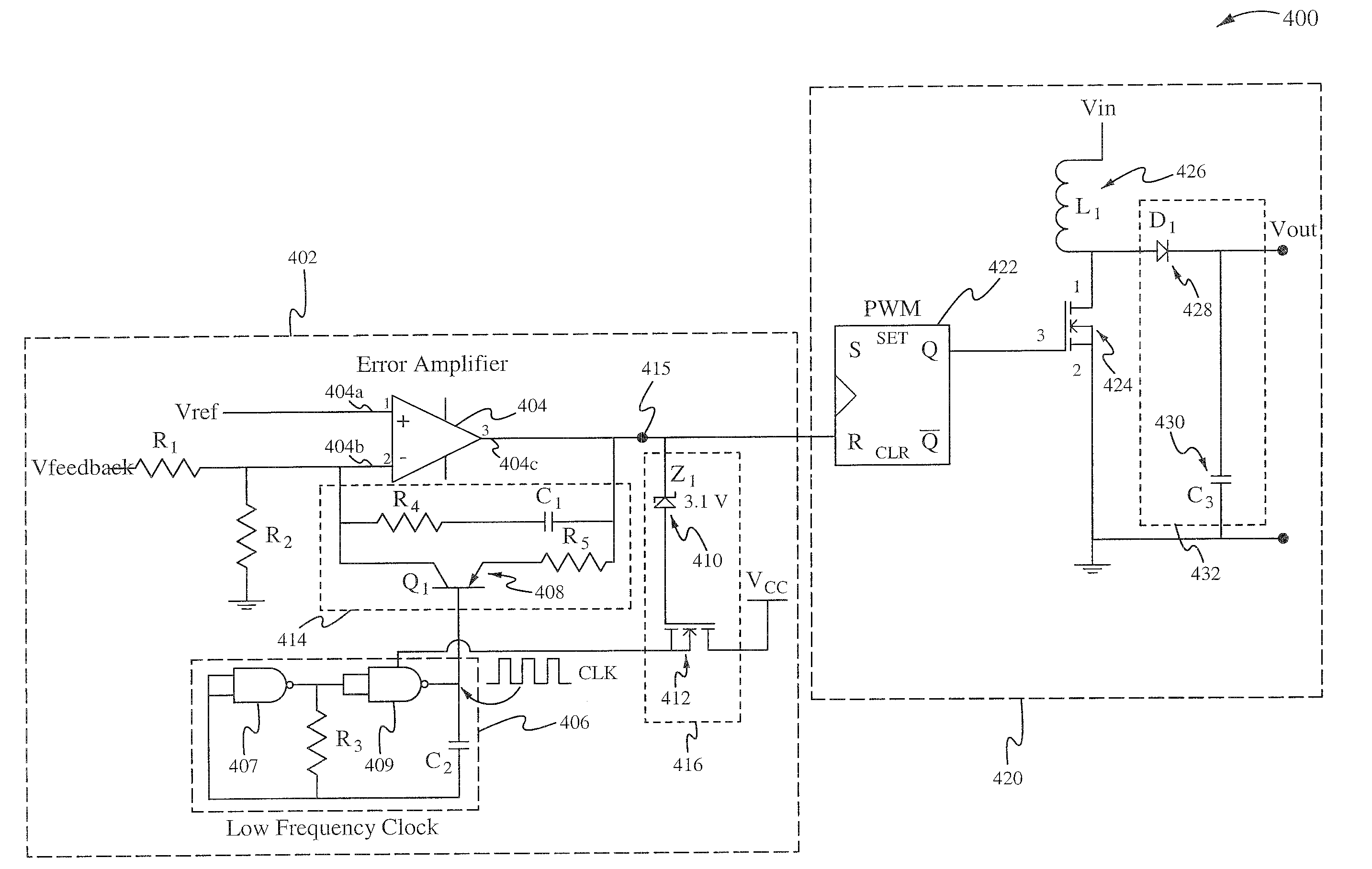
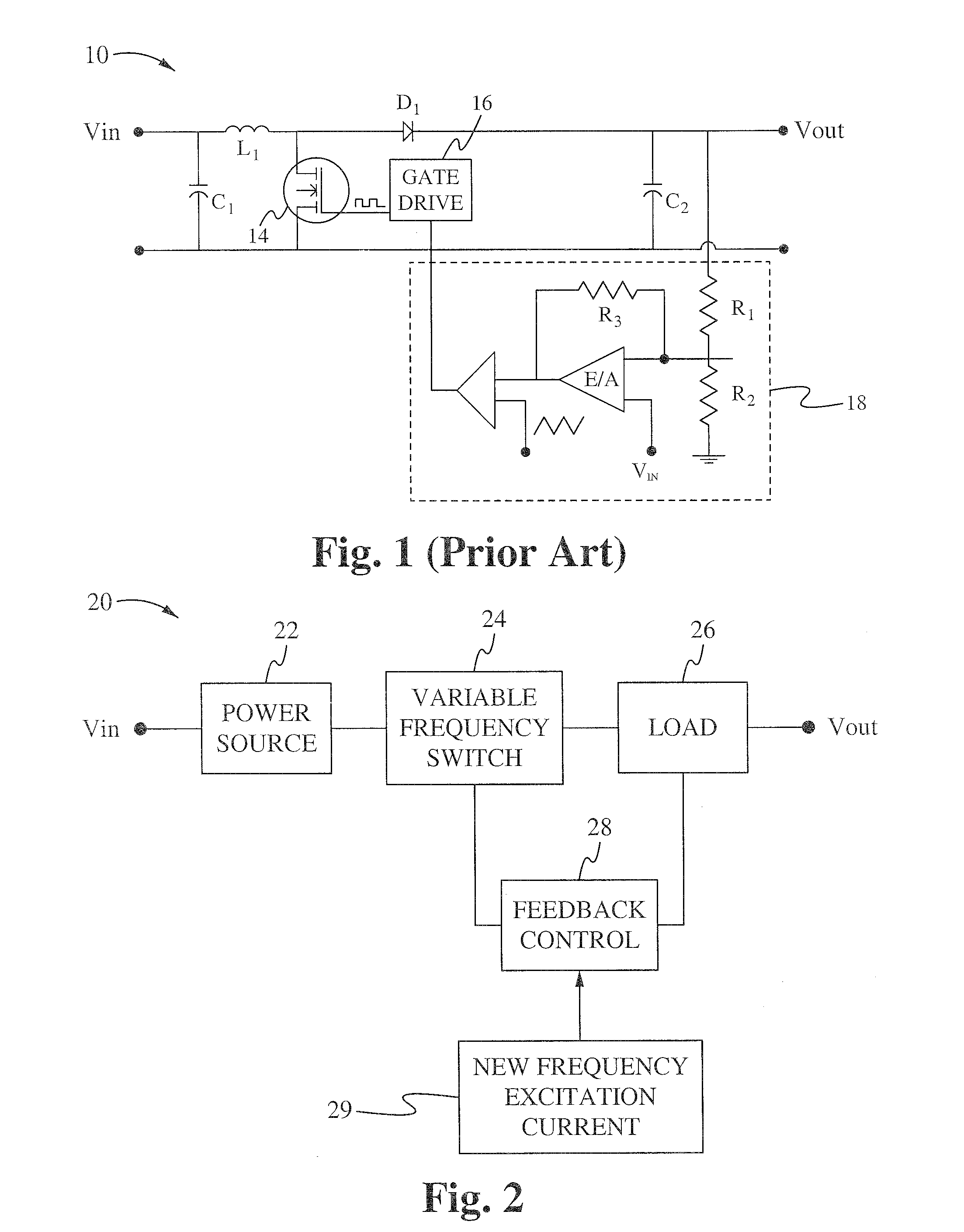
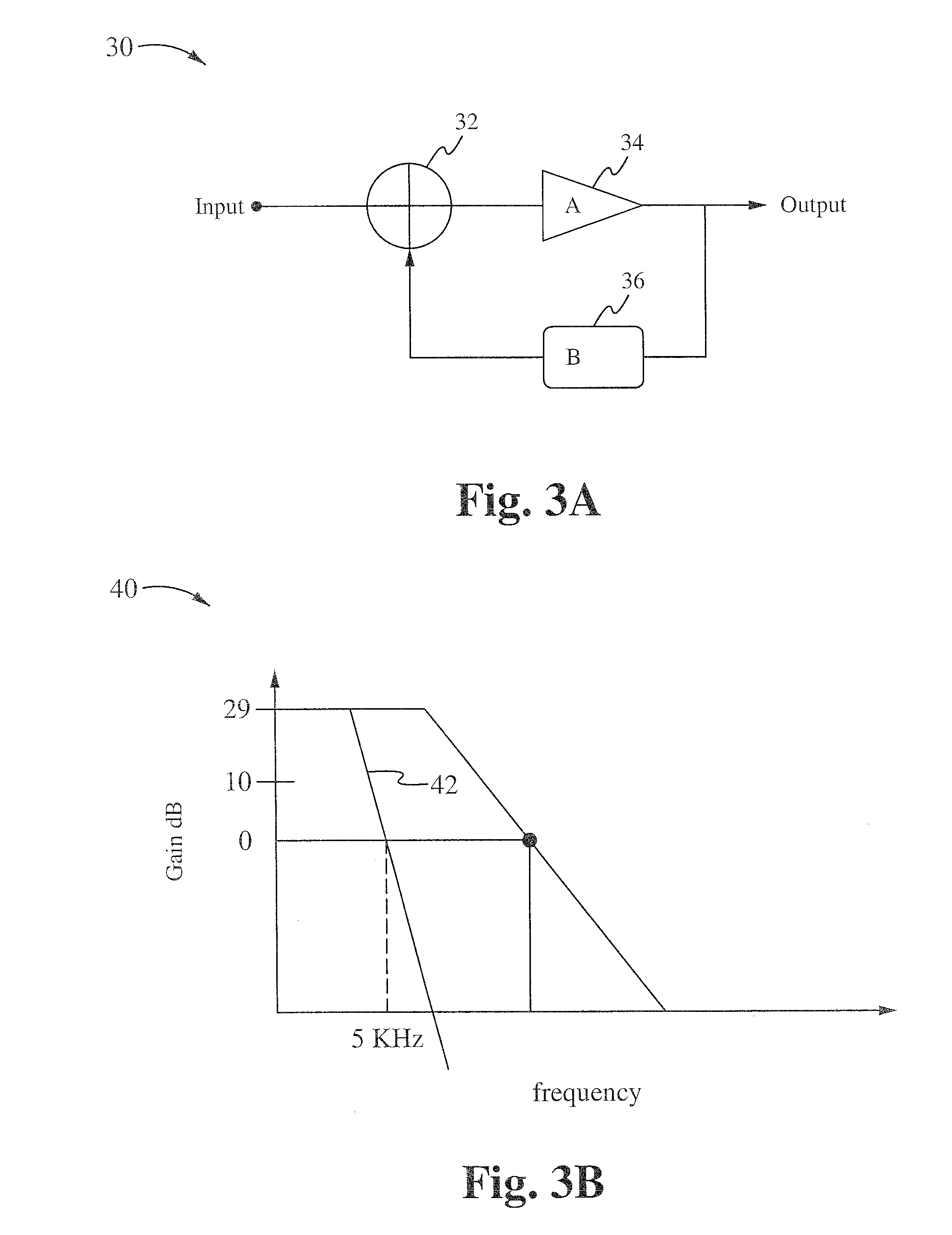
[0023]The present invention provides a technique to reduce EMI emission without reduction of switching frequency. The present invention allows a switching frequency to be higher without exhibiting unwanted high harmonic distributions and further facilitates transferring the high harmonic distributions to a frequency range below the standard EMI bandwidth, which is less than 150 Khz, by applying low frequency modulation into a feedback loop. The low frequency modulation is injected into the feedback loop and effects the rising and falling edges of switching pulses of a switc...


PUM


Abstract

A power supply apparatus and method of regulating is provided. A clock generator circuit is configured for generating a clock signal at a predetermined frequency. An amplifier circuit is coupled with the clock generator circuit. The amplifier circuit includes a gain circuit coupled with the clock generator circuit. The amplifier circuit is configured to receive the clock signal at a switching element of the gain circuit. A controller circuit is configured for receiving a modulated error signal of the amplifier circuit and is configured for generating a pulse width modulated signal for controlling a duty cycle of the switching circuit. The switching circuit is configured for receiving the modulated error signal. The error signal is modulated using the clock signal to vary a gain value of the gain circuit according to the predetermined frequency. An output circuit is coupled with the switching circuit and is configured for generating a regulated voltage signal. The controller circuit uses the modulated error signal to substantially reduce harmonic distribution in a switching frequency of the switching circuit. Harmonic distribution in the switching circuit can be reduce by 10.0 db or greater.

Description

FIELD OF THE INVENTION[0001]The present invention relates to the field of power supplies. More particularly, the present invention relates to a closed loop negative feedback system with low frequency modulated gain.BACKGROUND[0002]Every electrical device that connects with a power supply main is required not to pollute or transmit high frequency noise onto the main. The amount of electrical emission allowed by electrical devices is heavily regulated by the Federal Communications Commission (FCC). Conventional power supply designs have migrated to using higher operating frequencies since the higher operating frequencies allow a reduction in size of power supply components and allow a reduction is cost. The disadvantage of operating at higher frequencies is the increased production of high harmonics or electromagnetic interference (EMI).[0003]Conventional methods of reducing EMI has been aimed at reducing a switching frequency of a switching circuit below standard EMI bandwidth limits...

Claims


Application Information

Patent Timeline
IPC IPC(8): G05F1/10
CPCH02M1/12H02M3/155H02M1/44
Inventor TELEFUS, MARK
Owner FLEXTRONICS AP LLC
Why Eureka
Try Eureka