
Method for controlling energy storage type converter topology with fault ride-through capability

A fault ride-through and control method technology, applied in the direction of irreversible DC power input conversion to AC power output, AC power input conversion to DC power output, AC network voltage adjustment, etc., can solve the problem of not having energy storage function, etc. To achieve the effect of ensuring high-efficiency operation and safety, smooth charging and discharging current, and low voltage level

Active Publication Date: 2017-06-20
SHANGHAI JIAO TONG UNIV
View PDF8 Cites 6 Cited by
  • Summary
  • Abstract
  • Description
  • Claims
  • Application Information

AI Technical Summary

Problems solved by technology

In the event of a DC fault, DC fault ride-through is realized by blocking a part of the sub-modules, and provides reactive power support for the grid through another part of the sub-modules; this patent realizes fault ride-through by blocking the sub-modules and cooperating with the full bridge module and the clamping single sub-module, only Has the ability to ride through faults, but does not have the energy storage function in the event of a fault

Method used


Image

  • Method for controlling energy storage type converter topology with fault ride-through capability
  • Method for controlling energy storage type converter topology with fault ride-through capability
  • Method for controlling energy storage type converter topology with fault ride-through capability

Examples


Embodiment Construction

[0029] The present invention will be described in detail below in conjunction with specific embodiments. The following examples will help those skilled in the art to further understand the present invention, but do not limit the present invention in any form. It should be noted that those skilled in the art can make several modifications and improvements without departing from the concept of the present invention. These all belong to the protection scope of the present invention.

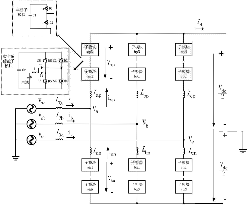
[0030] like figure 1 As shown, a modular multilevel converter topology with energy storage function includes three phase units; each phase unit x (x=a, b, c) includes an upper bridge arm, a lower bridge arm, Upper arm inductance L xp , Lower arm inductance L xn ;in:

[0031] The positive terminal of the upper bridge arm is used as the positive terminal of the DC outgoing line of the phase unit; the negative terminal of the upper bridge arm is connected with the inductance L of the upper bridge ...


PUM


Abstract

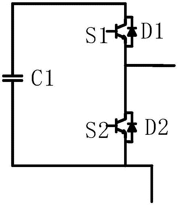
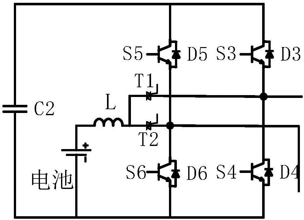
The invention discloses a method for controlling an energy storage type converter topology with fault ride-through capability, wherein the converter topology comprises three phase units, each phase unit comprises an upper bridge arm, a lower bridge arm, an upper bridge arm inductor and a lower bridge arm inductor, and each one of the upper bridge arms and the lower bridge arms of the three phase units is composed of a half-bridge sub-module and a quasi full-bridge energy storage sub-module, which are connected in series in a hybrid manner. The method comprises the following steps: determining modulating waves of each half-bridge sub-module and each quasi full-bridge energy storage sub-module in the bridge arm of each phase according to a to-be-output instruction voltage waveform of each phase, performing comparison according to carriers and modulating waves of each sub-module in the bridge arm of each phase to generate a control signal, and separately controlling the turn-on or turn-off of each sub-module in the bridge arm of each phase. The energy storage type converter topology with the fault ride-through capability can increase the inertia of a new energy system, the charging and discharging current of a battery used for energy storage is smooth, and the voltage level is relatively low, therefore the efficient operation and the safety of the battery are ensured. Meanwhile, the energy storage type converter topology has DC side fault ride-through capability and can still store energy in the case of DC side faults.

Description

technical field [0001] The invention belongs to the technical field of electrical automation equipment, and in particular relates to a control method for an energy storage converter topology with fault ride-through capability. Background technique [0002] In the existing technology, the sub-module with energy storage function directly connects the battery next to the capacitor of the sub-module, so that the battery can withstand the pulsating current of one or two times the power frequency, which has great impact on the efficient operation of the battery and the cost of the whole life cycle. Unfavorable; at the same time, the sub-module capacitor voltage in actual working conditions is generally greater than 1500V voltage level. For high-rate batteries represented by lithium-ion batteries, based on the balance of battery state of charge and fault protection, it is difficult to achieve in terms of cost and safety. Such a high series voltage. In addition, this sub-module wit...

Claims


Application Information

Patent Timeline
Patent Type & Authority Applications(China)
IPC IPC(8): H02M7/5387H02M7/5395H02M1/12H02J3/12
CPCH02J3/12H02M1/12H02M7/53871H02M7/5395H02M7/4835H02M1/0095H02M7/49
Inventor 李睿张弢王平
Owner SHANGHAI JIAO TONG UNIV
Learn More