Calibration Apparatus And Method For Optical System Assembly

a technology of optical system and calibration apparatus, which is applied in the manufacture of optical heads, instruments, measurement devices, etc., can solve the problems of easy impact on the height of the optical calibration system, the overall quality of the optical system is compromised, and the environment and vibration can affect the overall quality of the optical system. achieve the effect of optimizing the image heigh

Inactive Publication Date: 2010-11-18
TOPRAY MEMS
View PDF4 Cites 2 Cited by
  • Summary
  • Abstract
  • Description
  • Claims
  • Application Information

AI Technical Summary

Benefits of technology

[0005]The primary object of the present invention is to provide a calibration apparatus and method for optical system assembly. Through the calibration apparatus of the present invention provides, during the assembly of finite conjugate optical system, the opti...

Problems solved by technology

As the optical lens is widely applied and the demands on the calibration of optical system assembly, the error checking and estimation is an important issue for manufacturing high precision optical lens.
In the general optical system, if the optical axis of the lens does not coincide with the reference axis, there will be off-axis aberrations in the optical image forme...

Method used


Image

  • Calibration Apparatus And Method For Optical System Assembly
  • Calibration Apparatus And Method For Optical System Assembly
  • Calibration Apparatus And Method For Optical System Assembly

Examples


Embodiment Construction

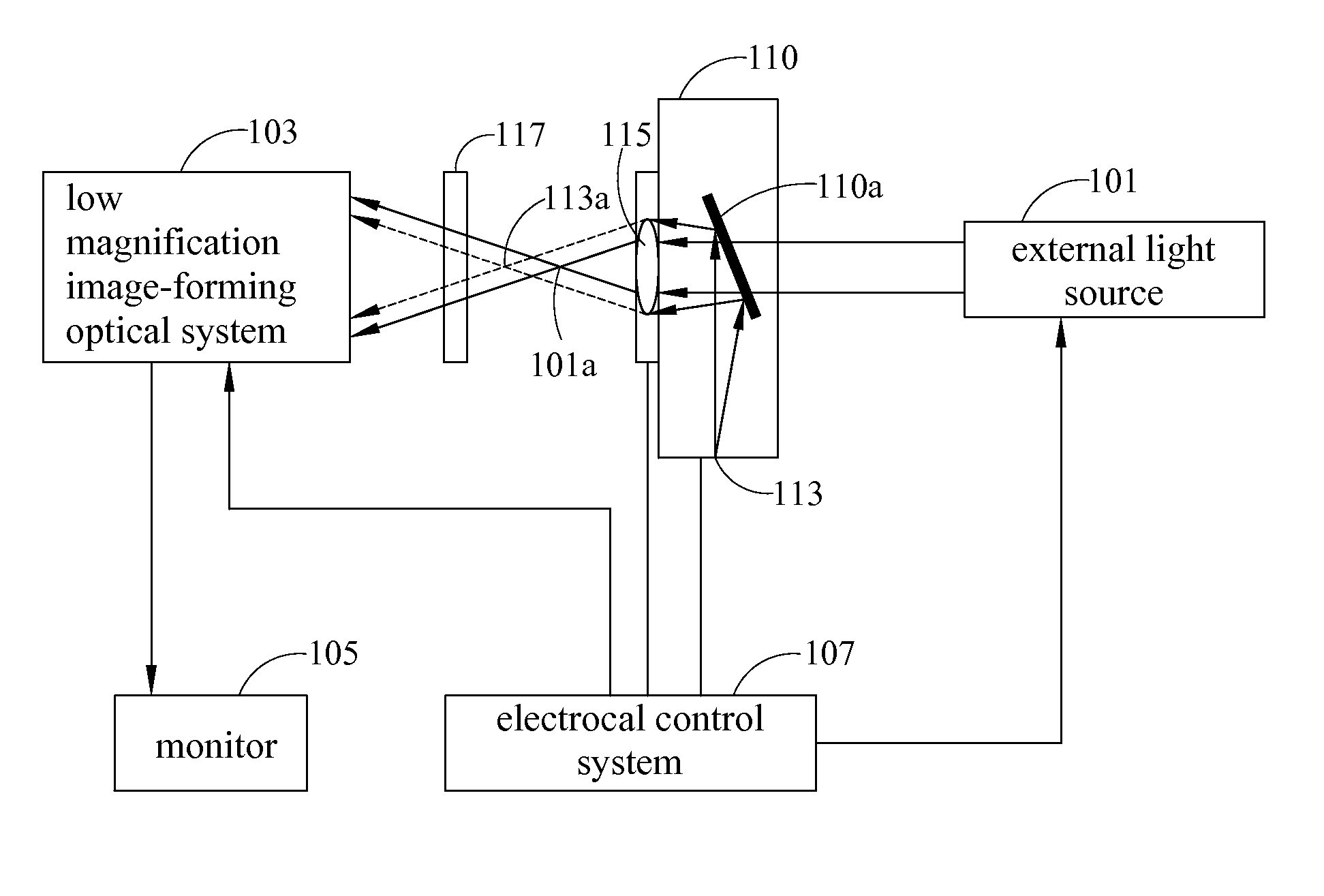
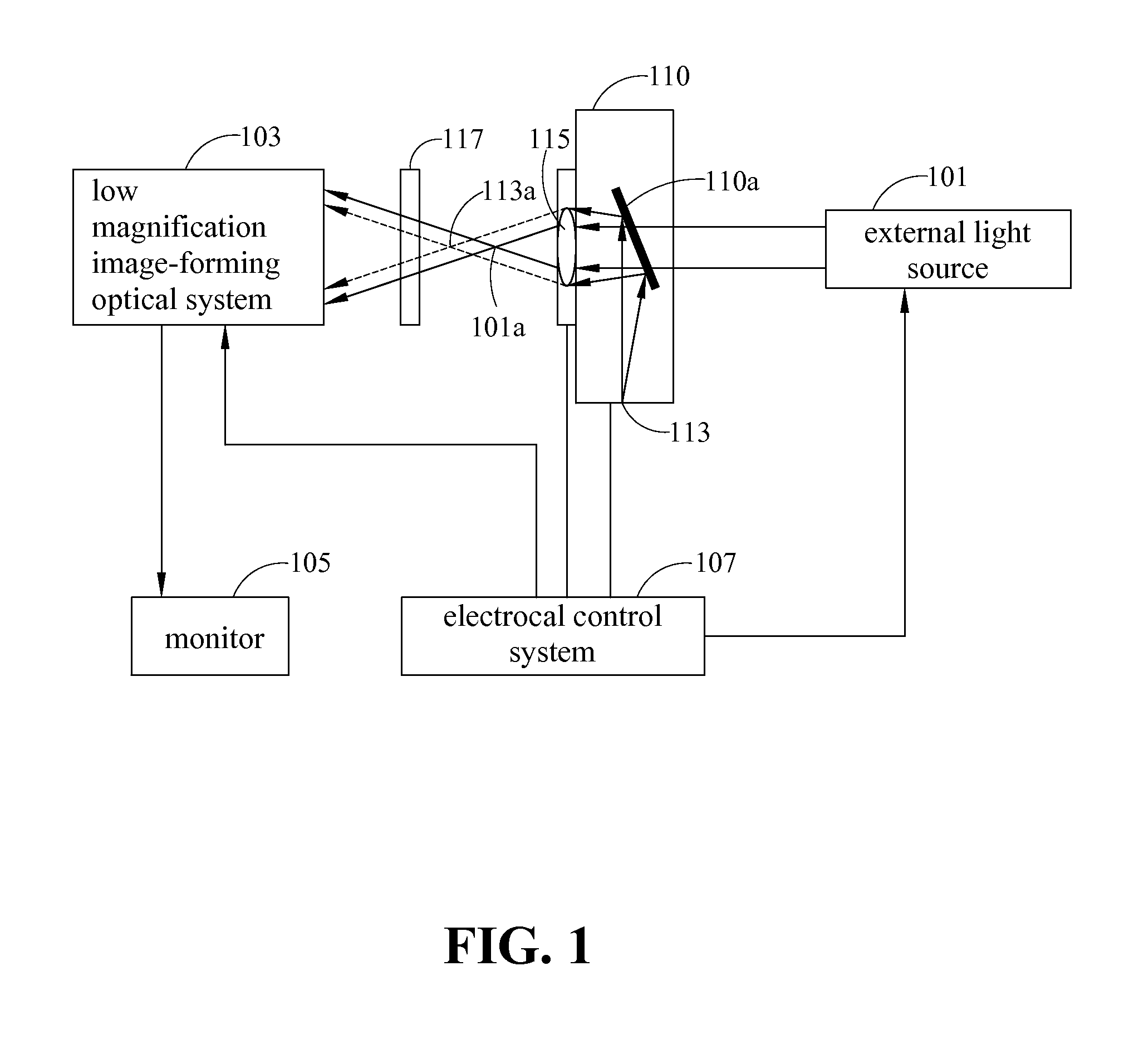
[0017]FIG. 1 shows a schematic view of a calibration apparatus for optical system assembly according to the present invention. The calibration apparatus is applied to a finite conjugate optical system 110 to find the optimal image-forming position between internal light source 113 and focus object lens 115. As shown in FIG. 1, the calibration apparatus for optical system assembly includes at least an external light source 101, a low magnification image-forming optical system 103 an electrical control system 107 and a monitor 105.

[0018]The parallel beam generated by external light source 101 of the calibration apparatus enters finite conjugate optical system 110 and forms a first focal spot 101a through focus object lens 115; electrical control system 107 activating internal light source 113 of finite conjugate optical system 110 and letting the beam from internal light source 113 form a second focal spot 113a through focus object lens 115; then, first focal spot 101a and second foca...


PUM


Abstract

A calibration apparatus and method for optical system assembly is provided, applicable to a finite conjugate optical system to determine the optimal image-forming positions of the light source and the focus object lens of the finite conjugate optical system. The apparatus includes an external light source, a low magnification image-forming optical system, an electrical control system and a monitor. When the parallel beam generated by the external light source is parallel to the optical axis of the finite conjugate optical system, the low magnification image-forming optical system is used to magnify the two focal spots formed by the external light source and the internal light source of the finite conjugate optical system to be calibrated. Finally, by adjusting the related position of the focus object lens or the internal light source of the finite conjugate optical system, the optimal relative positions between the light source and the focus object lens of the finite conjugate optical system can be found. The calibration apparatus of the present invention has the advantages of simple structure, easy assemble and setup, high precision assembly and low cost, as well as the capability to perform optimal calibration of the relative position of the focus object lens and the light source of each individual finite conjugate optical system.

Description

FIELD OF THE INVENTION[0001]The present invention generally relates to a calibration apparatus and method for optical system assembly, applicable to calibrating the optimal imaging position between optical source and the focusing object lens of a finite conjugate optical system when assembling the finite conjugate optical system.BACKGROUND OF THE INVENTION[0002]The optical lens, such as the reader head of the CD player, digital camera, mobile phone camera and optical communication device, is in wide demands. As the high precision molding industry, such as glass molding and injection molding, rapidly progresses, the axis-symmetrical optical components must overlap the optical axis and the rotational symmetrical axis during the manufacturing or system assembly to avoid off-axis aberration errors. As the optical lens is widely applied and the demands on the calibration of optical system assembly, the error checking and estimation is an important issue for manufacturing high precision o...

Claims


Application Information

Patent Timeline
IPC IPC(8): G01B9/00
CPCG11B7/22G02B27/62
Inventor YANG, TSUNG-MINLU, WEI-CHIH
Owner TOPRAY MEMS
Why Eureka
Try Eureka