Wind turbine blade and hub assembly

a technology of wind turbine blades and hubs, applied in the direction of bearing units, machines/engines, wind energy generation, etc., can solve the problems of not optimally exploiting wind forces, and achieve the effect of better wind power extraction

Active Publication Date: 2010-11-18
LM GLASSFIBER
View PDF5 Cites 30 Cited by
  • Summary
  • Abstract
  • Description
  • Claims
  • Application Information

AI Technical Summary

Benefits of technology

[0005]It is therefore an object of the present invention to provide a blade for a wind energy plant and a hub assembly and design allowing for a better wind power extraction in the region close to the hub, and where some of the above-mentioned disadvantages are overcome or reduced.

Problems solved by technology

The disadvantage of the root section is of course that the wind forces are not optimally exploited in this region closest to the hub.

Method used


Image

  • Wind turbine blade and hub assembly
  • Wind turbine blade and hub assembly
  • Wind turbine blade and hub assembly

Examples


Embodiment Construction

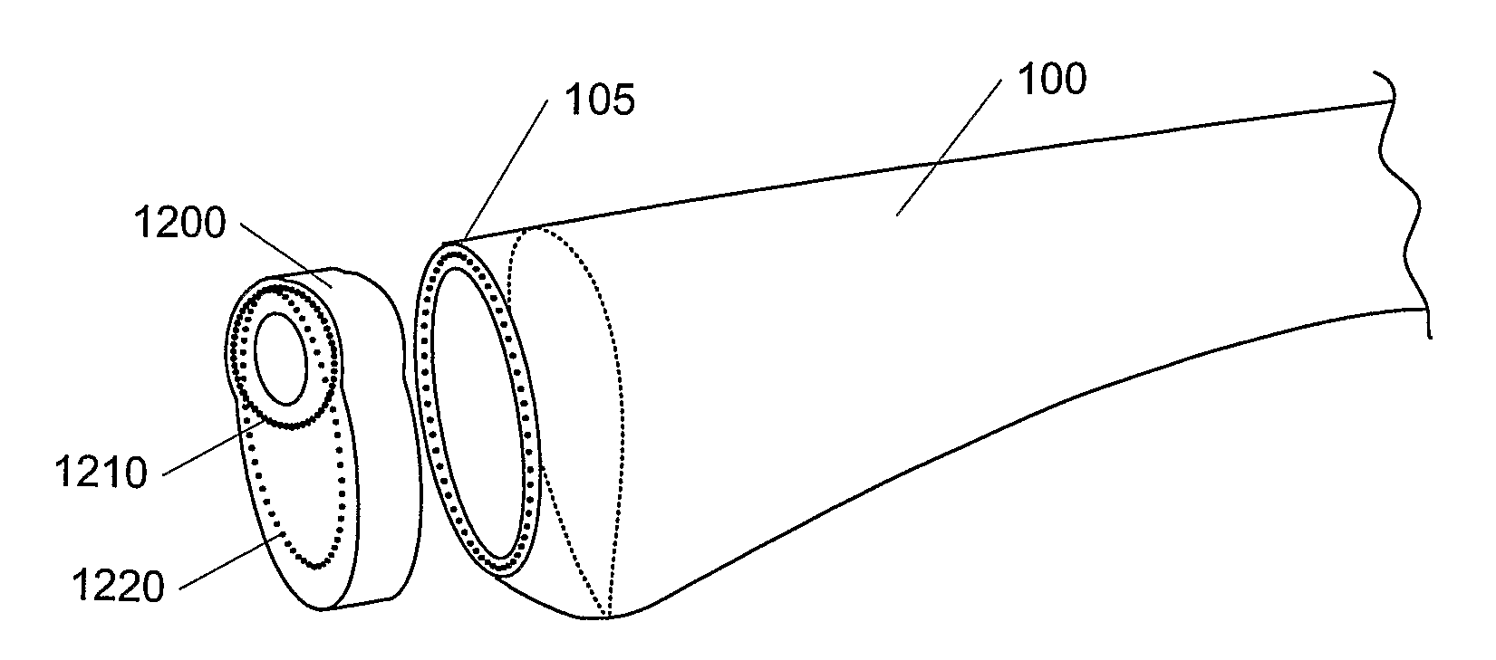
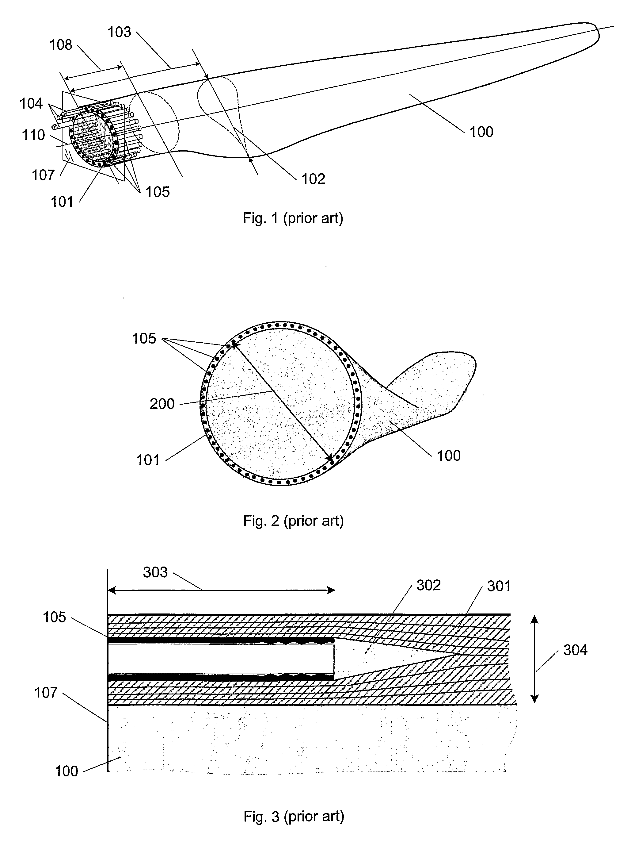
[0038]FIG. 1 shows, in a perspective view, a wind turbine blade 100 of which the most part is shaped according to aerodynamics to maximize the power uptake from the wind. The blade part from the root 101 to where the aerodynamical profile attains its maximum chord 102 is here and in the following referred to as the root section 103 of the blade. This section is generally shaped both with a view to aerodynamics, but also and primarily so that the blade assembly to the hub is optimally ensuring the best possible load transfer and minimal risk of damage and minimal wear of the blade, the fastening members 104 and the bearings in the hub. The blade is most often connected to the hub by a number of fastening members such as rods, studs, threaded bars and nuts, or bolts 104 (of which only a few are drawn for clarity) that are inserted into bushings 105 in the root section 103. If threaded bars are used, they might also be directly embedded into the blade laminate. The root end 101 is most...


PUM

PropertyMeasurementUnit
angleaaaaaaaaaa
lengthsaaaaaaaaaa
rotational forcesaaaaaaaaaa

Abstract

This invention relates to a wind turbine blade with at least two connection members such as bushings and/or threaded bars in the root of the blade for attaching the blade to a hub. The connection members are placed along the blade surface and at least some of the connection members are non-parallel and hence oriented in different directions. Hereby is obtained that the root section of the blade can be shortened and the maximum chord of the wind turbine blade can be moved closer to the hub, whereby the part of the blade exploiting the wind is increased and the power output similarly increased.
The present invention further relates to a pitch bearing and a hub comprising a bearing ring with two or more holes for positioning fastening members for attaching a wind turbine blade to the bearing. Here, correspondingly, at least two of the holes are oriented in different angles so that the fastening members positioned in the holes are non-parallel and extend in different directions.

Description

FIELD OF THE INVENTION[0001]The present invention concerns a turbine blade for a wind energy plant and its connection to a bearing and a hub for a wind power installation.BACKGROUND[0002]The blades for a wind energy plant are for the most part shaped as aerodynamical profiles in order to exploit the wind power optimally. The blades are connected to the hub often via one or more bearings, whereby the loads are transferred to the hub and to a certain degree to the rotor shaft. The loads comprise both the (intentional) rotational forces, centrifugal forces, gravity forces and forces, loads and moments arising out of the action of the wind on the rotor blades. The wind turbine blades can be rigidly connected to the hub, but most modern wind turbines can regulate and adjust the position of the blades for instance by pitch regulation and / or by coning. Therefore, the blades are often connected to the hub via bearings of some kind, for instance a circular pitch bearing allowing each blade t...

Claims


Application Information

Patent Timeline
Patent Type & Authority Applications(United States)
IPC IPC(8): F03D11/04F03D11/00B23P15/04
CPCY02E10/721F16C19/18F05B2260/301F16C35/06F03D1/0658F16C2300/14Y02E10/722Y10T29/49336F16C2360/31Y02E10/72
Inventor SORENSEN, TOMMY
Owner LM GLASSFIBER
Why Eureka
Try Eureka