
Centrifugal force-based microfluidic device for blood chemistry analysis

a microfluidic device and centrifugal force technology, which is applied in the direction of fluid speed measurement, positive displacement liquid engine, optical light guide, etc., can solve the problems of large and expensive equipment, difficult to perform various kinds of examinations at the same time, and large amount of blood required for conventional pathological examinations

Active Publication Date: 2010-11-18
PRECISIONBIOSENSOR INC
View PDF3 Cites 29 Cited by
  • Summary
  • Abstract
  • Description
  • Claims
  • Application Information

AI Technical Summary

Benefits of technology

[0012]The present invention also provides a microfluidic device that can readily perform biochemical tests of a blood sample by using various kinds of currently commercially available reagents without or with a minimal amount of processing.
[0014]Also, the present invention provides a microfluidic device that can store at least two reagents in separate chambers and can mix the reagents immediately before being used.

Problems solved by technology

Conventional pathological examinations require a lot of work and various kinds of equipment.
However, regardless of the skill of clinical pathologists, it is difficult to perform various kinds of examinations at the same time.
In the case of a conventional blood test, large and expensive equipment, which requires a relatively large amount of blood, is used.
However, most of these apparatuses require that serum is separated from blood sample and then diluted before performing the tests.
Furthermore, as it is difficult to provide samples diluted at different ratios, the dilution ratio of a sample is maintained constant, and the concentration or size of reagent beads and a size of a reaction chamber are varied to attain differently diluted samples.
The necessity of frozen-dried reagent beads and of the reaction chambers of different sizes depending on the kind of reagents has complicated the design and construction of a microfluidic device.
Therefore, there are many difficulties in providing a disk type microfluidic device that can use currently commercially available reagents.

Method used


Image

  • Centrifugal force-based microfluidic device for blood chemistry analysis
  • Centrifugal force-based microfluidic device for blood chemistry analysis
  • Centrifugal force-based microfluidic device for blood chemistry analysis

Examples


Embodiment Construction

[0031]The present invention will now be described more fully with reference to the accompanying drawings in which exemplary embodiments of the invention are shown.

[0032]While the description of the invention focuses on the blood analysis, the device of the invention are suitable for the analysis of any liquid, typically a biological sample such as whole blood or plasma, urine, sputum, semen, saliva, ocular lens fluid, cerebral fluid, spinal fluid, amniotic fluid.

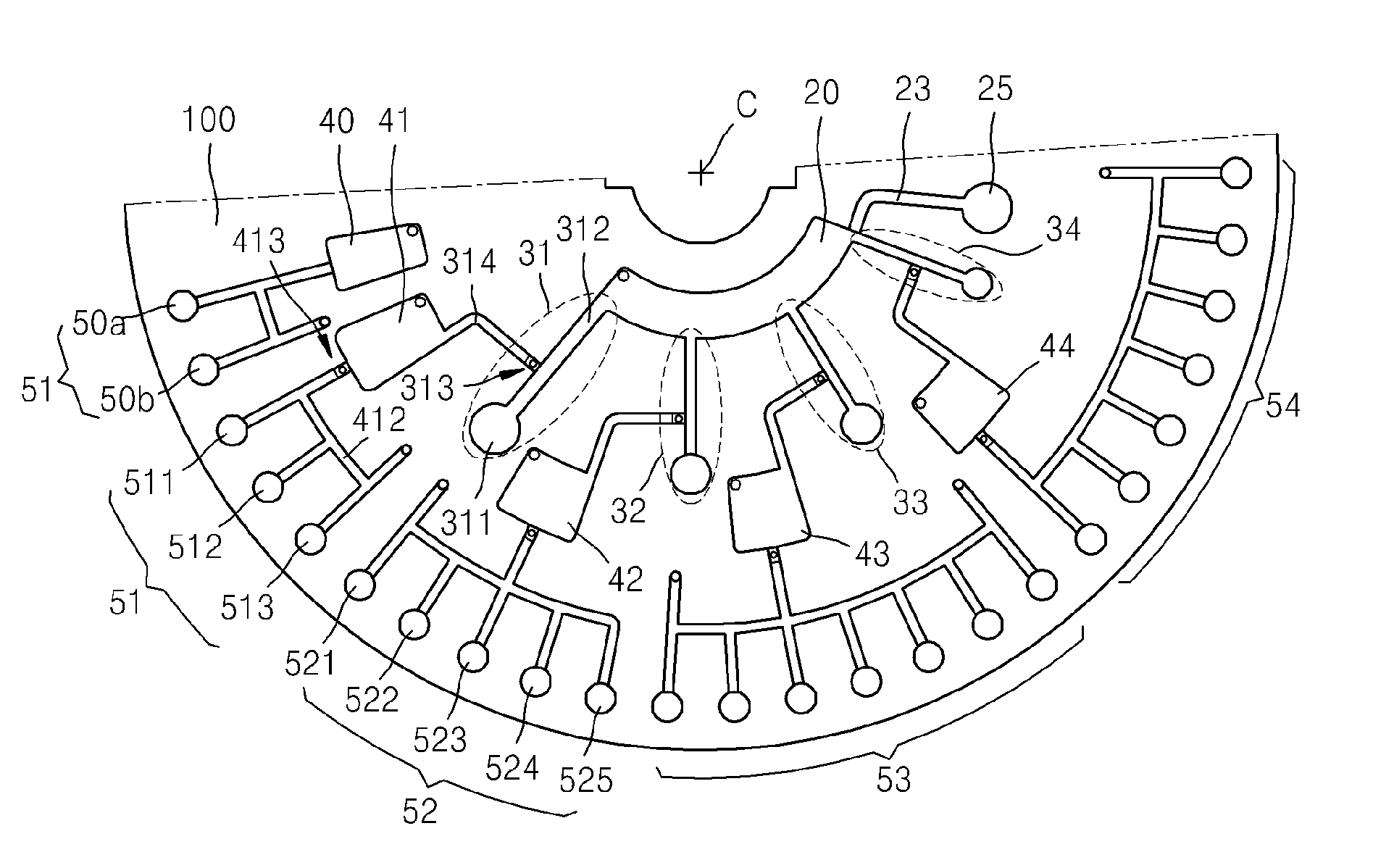
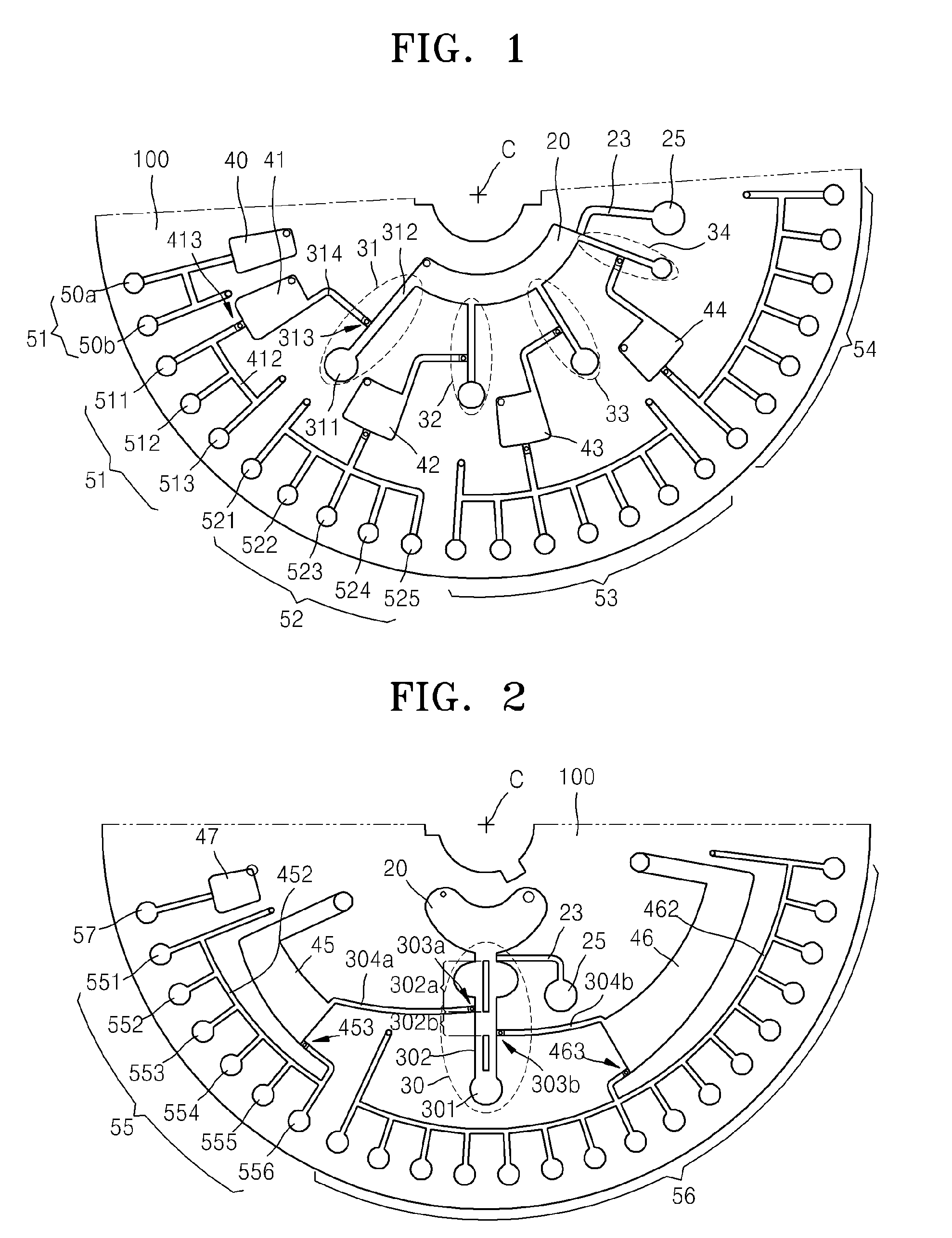
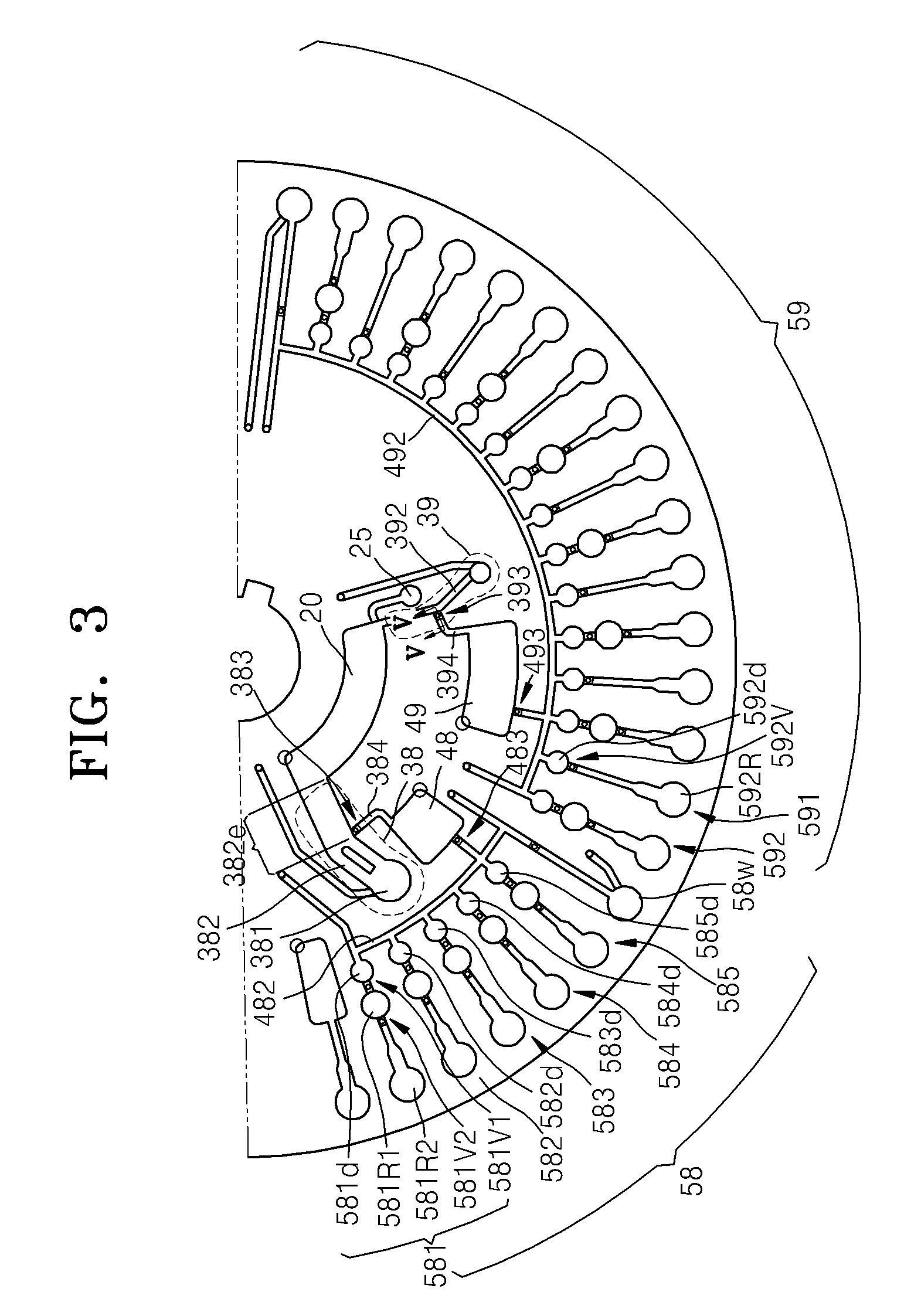
[0033]FIG. 1 is a plan view of a centrifugal force-based microfluidic device for blood analysis according to an embodiment of the present invention. The centrifugal force-based microfluidic device includes a rotatable platform 100 and structures that provide spaces for accommodating fluids and flow channels through which the fluids can flow. The disk type platform 100 can be a shape of a disk and rotated with respect to the center C thereof. In the structures disposed in the disk type platform 100, moving of a specimen, cent...


PUM


Abstract

Provided is a microfluidic device that can automatically perform various types of biological blood analysis. In the microfluidic device, a specimen is centrifugally separated and the centrifugally separated specimen is diluted into various dilution ratios. Also, at least two reagents that are required for one reaction and that need to be separately stored are stored in separate chambers, and they are mixed when a reaction is needed. Thus, various conventional blood analyzing reagents can be used as they are or after being minimally processed in the microfluidic device.

Description

CROSS-REFERENCE TO RELATED PATENT APPLICATION[0001]The present application is a Divisional of U.S. application Ser. No. 12 / 146,523 filed Jun. 26, 2008 (now allowed), which claims the benefit of Korean Patent Application No. 10-2007-0084522, filed on Aug. 22, 2007, in the Korean Intellectual Property Office, the disclosures of which are incorporated herein in their entireties by reference.BACKGROUND OF THE INVENTION[0002]1. Field of the Invention[0003]The present invention relates to a centrifugal force-based microfluidic device, and more particularly, to a centrifugal force-based microfluidic device that can be used for chemical analysis of blood, in which various kinds of biochemical reactions can take place using samples having different mixing ratios or reagents with different preparation conditions.[0004]2. Description of the Related Art[0005]A microfluidic structure that performs an independent function in a microfluidic device generally includes chambers that can contain a flu...

Claims


Application Information

Patent Timeline
Patent Type & Authority Applications(United States)
IPC IPC(8): G01N1/38B81B1/00G01N33/48
CPCB01L3/502753Y10T436/25375B01L2200/0642B01L2200/0684B01L2200/10B01L2200/16B01L2300/0806B01L2300/0864B01L2300/087B01L2400/0409B01L2400/0622B01L2400/0677G01N33/491G01N33/54313G01N35/00069Y10T436/25125Y10T436/2575Y10T436/111666B01L2200/0605G01N33/49G01N33/48G01N35/00G01N33/00
Inventor CHO, YOON-KYOUNGKIM, DO-GYOONLEE, JUNG-NAMLIM, HEE-KYUN
Owner PRECISIONBIOSENSOR INC
Learn More