Method and device for plasma-supported surface treatment

a technology of plasma-supported surface and treatment method, which is applied in the direction of electrostatic cleaning, chemical vapor deposition coating, application, etc., can solve the problems of high operating cost, complicated power supply device, and only possible use of low-pressure plasma methods for large-scale technical applications

Inactive Publication Date: 2010-11-18
LEIBNIZ INST FUR PLASMAFORSCHUNG & TECH
View PDF5 Cites 27 Cited by
  • Summary
  • Abstract
  • Description
  • Claims
  • Application Information

AI Technical Summary

Problems solved by technology

Due to the high system costs for the vacuum apparatuses required for this, the discontinuous method of operation, as well as because the dimensions of the work pieces to be treated are restricted by the size of the recipient used, use of low-pressure plasma methods for large-scale technical applications is only possible with restrictions, particularly in industrial line production.
Complicated, expensive power supply devices are needed.
Relatively high operating costs result from high energy consumption and, in part, also from a high gas consumption and from required cooling.
Uniform treatment (particularly coating) of the material is made difficult by the non-homogeneous structure of the plasmas.
In many cases, the discharges are non-homogeneous and consist of many small, energy-rich micro-discharges, which can lead to local material damage.
The devices cannot be used universally for simply any work pieces.
Either they are suitable only for treatment of planar materials having a material thickness restricted to a few millimeters (such as foils and web materials, for example), or they can only be adapted to work pieces having a complex geometry by means of complicated positioning systems.
The devices cannot be used as manual devices for manually guided operation.

Method used


Image

  • Method and device for plasma-supported surface treatment
  • Method and device for plasma-supported surface treatment
  • Method and device for plasma-supported surface treatment

Examples


examples

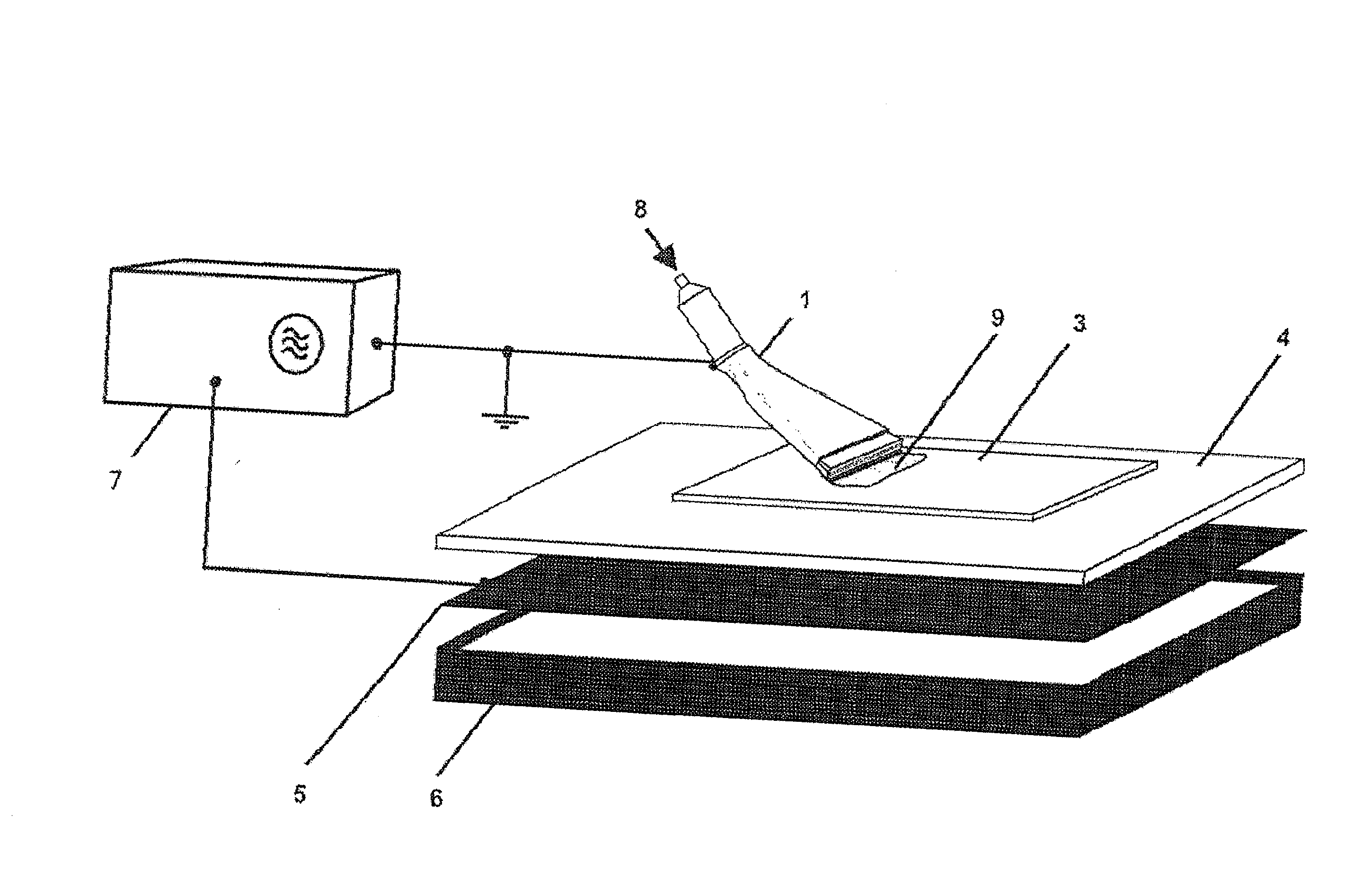
[0103]The invention and its application possibilities are explained in greater detail with the exemplary embodiments shown below in different drawings. The following reference symbols are used to identify the individual elements of the structure of the devices:

Reference Symbol List:
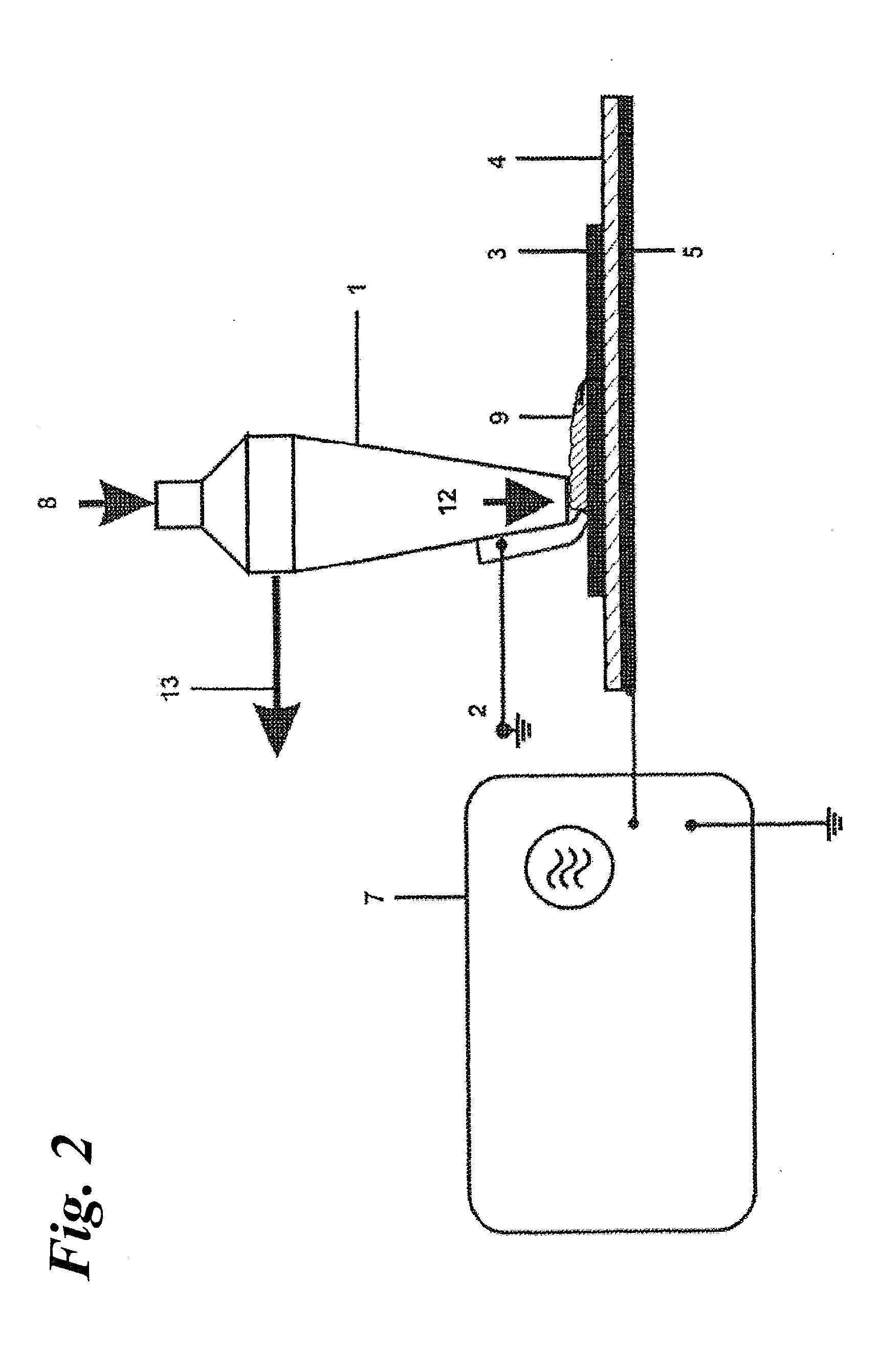
[0104]1 gas nozzle

[0105]2 grounded contact electrode

[0106]3 work piece

[0107]4 insulator (dielectric or ferroelectric)

[0108]5 high-voltage electrode

[0109]6 insulation

[0110]7 high-voltage source

[0111]8 gas feed

[0112]9 surface plasma

[0113]10 housing with high-voltage supply

[0114]11 motor with magnetic clutch

[0115]12 gas exit

[0116]13 movement direction

[0117]14 joining edge

[0118]15 second nozzle channel

[0119]16 suction device

[0120]17 precursor feed

[0121]18 rotating brush

[0122]19 hinge

[0123]20 handle piece with plug connector

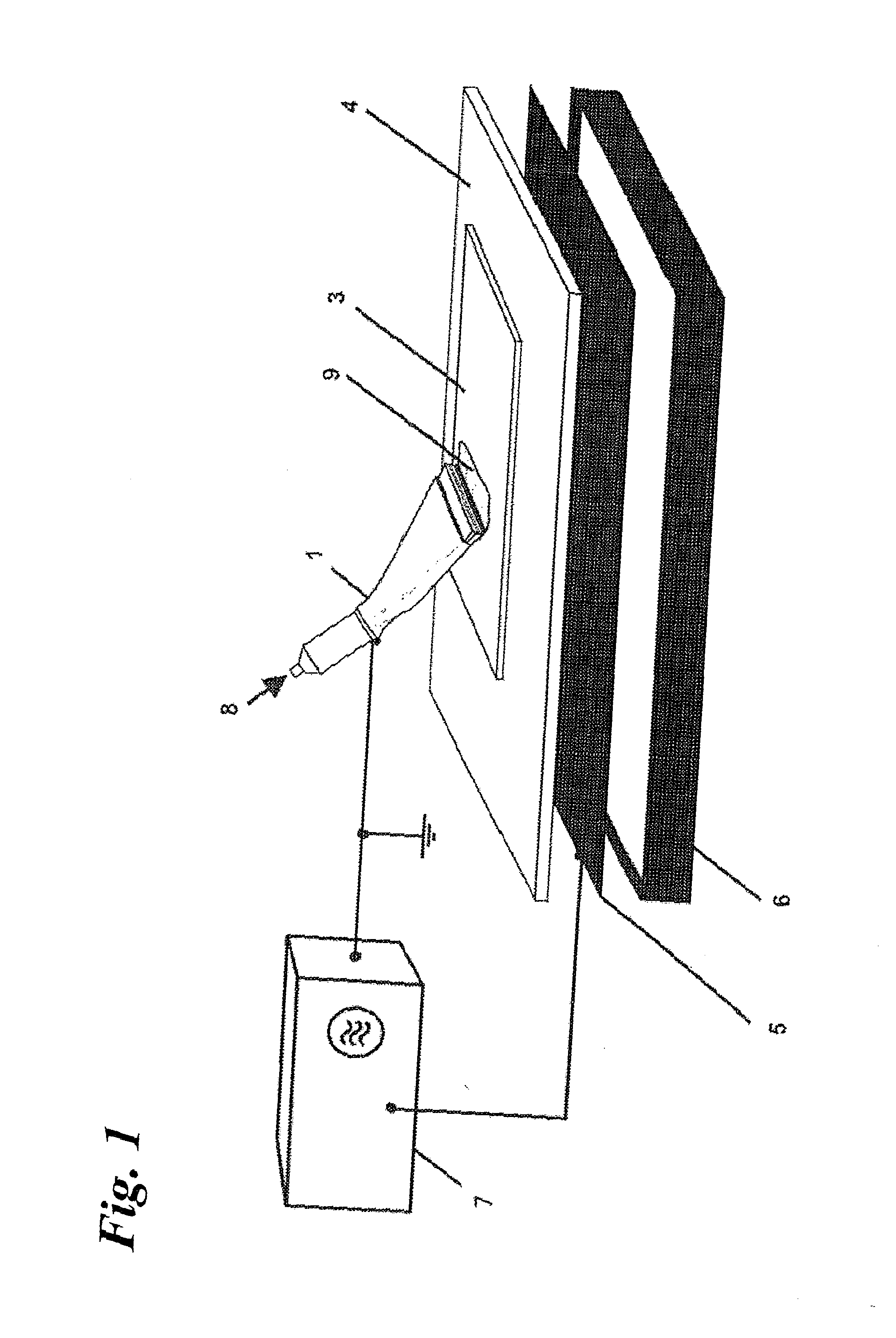
[0124]FIG. 1 shows the fundamental structure of the device having a planar high-voltage electrode (5) covered with a dielectric or ferroelectric (4), as well as having a gas nozzle (1) conf...


PUM

PropertyMeasurementUnit
lengthaaaaaaaaaa
frequencyaaaaaaaaaa
atmospheric pressureaaaaaaaaaa

Abstract

A method and a series of devices for dry cleaning, activating, modifying, coating, and biologically decontaminating (degerming, disinfecting, sterilizing) surfaces by means of an atmospheric pressure plasma generated using a surface barrier discharge are provided. The invention is used for dry cleaning, activating, coating, modifying, and biologically contaminating surfaces by means of an atmospheric pressure plasma generated in a defined, flowing gas atmosphere by a surface barrier discharge, comprising a high-voltage electrode that is covered with a dielectric or ferroelectric material, an electrically conducting grounded contact electrode, a high-voltage supply, a gas supply, and a gas nozzle (encompassing a gas outlet); said gas nozzle is located in the direct vicinity of the grounded contact electrode, is integrated into the contact electrode, or acts as the grounded contact electrode.

Description

BACKGROUND OF THE INVENTION[0001]1. Field of the Invention[0002]The invention relates to a method and to a series of devices for dry cleaning, activation, coating, modification, and biological decontamination (such as degerming, disinfection, sterilization) of surfaces by means of an atmospheric pressure plasma produced by means of so-called surface barrier discharge.[0003]2. Description Of The Related Art[0004]Plasma technology methods can already be used, in standard manner, for treating material surfaces with the goal of cleaning (i.e. decontaminating), activating, functionalizing or coating the surface, in order to prepare it for subsequent technological processes, such as gluing, printing, varnishing, or to be able to carry work out under germ-free conditions. In the past, low-pressure plasmas were primarily used for this, particularly for complex surface geometries. Due to the high system costs for the vacuum apparatuses required for this, the discontinuous method of operation...

Claims


Application Information

Patent Timeline
Patent Type & Authority Applications(United States)
IPC IPC(8): A61N1/00H05H1/00H05H1/24C23C16/513C23C16/40B01J19/08A61L2/14
CPCB05D3/141B05D7/146B29C59/14B29C59/142H01J37/32825H01J37/3244H01J37/32541H01J37/3255H01J37/32348A61B18/042A61P17/00A61P17/02A61N1/0468
Inventor EHLBECK, JOERGFOEST, RUEDIGERKINDEL, ECKHARDLEMBKE, NORBERTSTIEBER, MANFREDWELTMANN, KLAUS-DIETER
Owner LEIBNIZ INST FUR PLASMAFORSCHUNG & TECH
Why Eureka
Try Eureka