VTOL lifting body flying automobile

a technology of lifting body and flying automobile, which is applied in the direction of steering devices, bicycle equipment, aircraft convertible vehicles, etc., can solve the problems of low efficiency of airflow deflecting devices, limited ability to manage load shifts on aircrafts, and low efficiency of such devices, so as to reduce the effect of mechanical interactions and reduce the number of components

Inactive Publication Date: 2010-11-25
JIANU LAURENTIU
View PDF56 Cites 34 Cited by
  • Summary
  • Abstract
  • Description
  • Claims
  • Application Information

AI Technical Summary

Benefits of technology

[0021]The primary object of the invention is to provide a simpler, robust, and more efficient roadable aircraft than existing versions by using engineering tactics and techniques of reduced number of components, lesser moving parts and minimizing mechanical interactions together with their decreased aerodynamic interferences.

Problems solved by technology

Disadvantages of prior art are due to lacking components and ways for sustaining lift or for fast recovery from situations of vehicle siderolled positions, also of unsafe handling at high incidence angles which lead to fore or aft induced craft dives, the conclusions being based on shown unsatisfactory thrust vectoring ranges and vectors in three dimensions.
A major disadvantage has the type of mechanism made of airflow deflecting multiple vanes or slots used to perform thrust vectoring.
Large mechanical stresses on these small size parts and on their support structures require constant maintenance, and performance of such devices has low efficiency because of resulted divergent, turbulent outflows.
A critical disadvantage of prior technology is the limited ability to manage loads shifts on aircrafts, especially rapid occurring ones in three dimensions.
All these increase craft building costs and complicate handling with each added part, including raised demands and discomfort to the pilot-driver attention levels.
An inadequacy of many Thrust Vectoring vehicles is their maneuvering ability.
Employment of pivotable nacelles or similar mechanisms limits them to slow transitions between the various orientations needed, and restricts those components movements ranges.
Aside from considerable clearance areas demanded for these external or internal structures motions, considerable space is necessary for unobstructed air intake during shifts in incidence angles.
Turbulence, slipping off the streams are conditions produced inside the compartments enclosing the propellers, causing the overall safety and efficiency to be compromised.
Lacking sufficient balance qualities is an issue for a lot of the disclosed flying cars.
Configurations with numerous airflow deflecting surfaces have lead to obstacles of synchronizing not just the terminal parts, but their connective networks of many actuators, transmissions, engines regimes and controls.
Instead of a stable aircraft, a highly sensitive platform to many sources had resulted, exposing it to added influences and vulnerable to the multiple factors interfering with one another.
These machines have proven decreased tolerance to small mechanical misalignments, to outer cross directional airflows, and produced imbalancing effects, being rocked forward to aftward, also induced lateral ‘wobbling ’ motions.
Insufficient versatility is the weakness of other prior inlets technologies.
Known roadable aircrafts are equipped with openings of single plane orientations thus resulting in absence of ruggedness, and lacking reliability to successfully handle multi directional, diverse pathways or non streamline inflows.
As predominant car operating platforms with secondary or minimal aerial transport capabilities, these machines rely too extensively on propulsion devices to attain some measure of multiple directions dynamics, but actually only produce restricted stability in three dimensional trajectories.
Just as important, these disclosed vehicles do not have enough lift producing features, do not gain effective lift in forward motion, nor are capable in power out situations to slower descent rate for reasonable crash survival.

Method used


Image

  • VTOL lifting body flying automobile
  • VTOL lifting body flying automobile
  • VTOL lifting body flying automobile

Examples


Embodiment Construction

[0080]Detailed descriptions of the preferred embodiment are provided herein, it is to be understood however that the present invention may be embodied in various forms. Therefore, specific details disclosed herein are not to be interpreted as limiting, but rather as a basis for the claims and as a representative basis for teaching one skilled in the art to employ the present invention in virtually any appropriately detailed system, structure or manner.

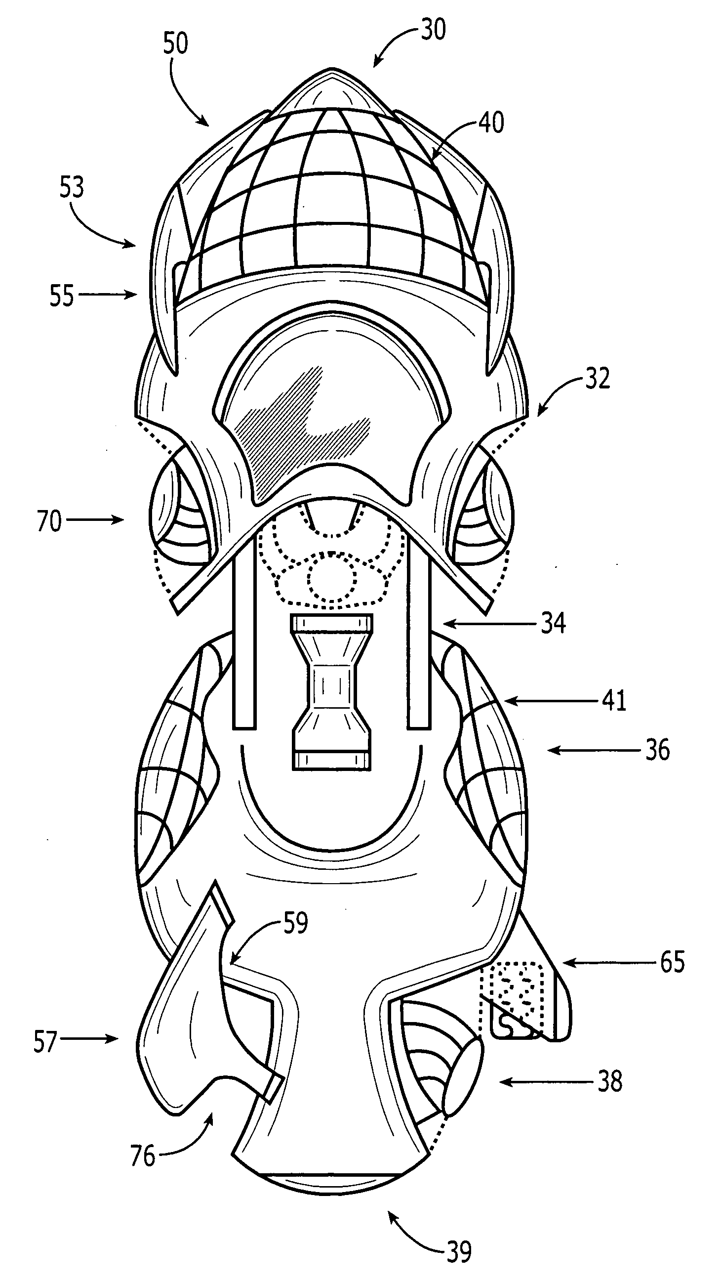
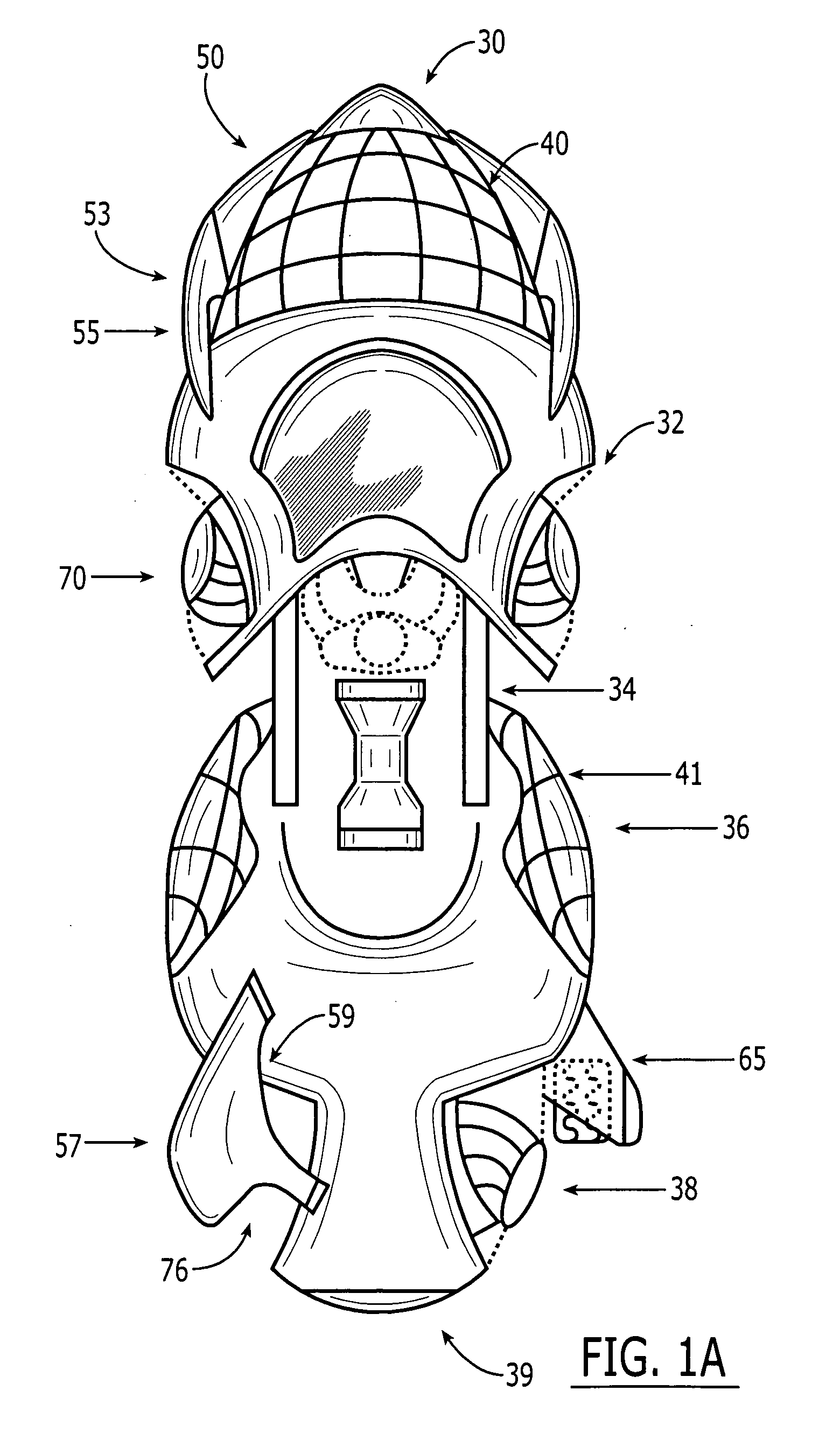
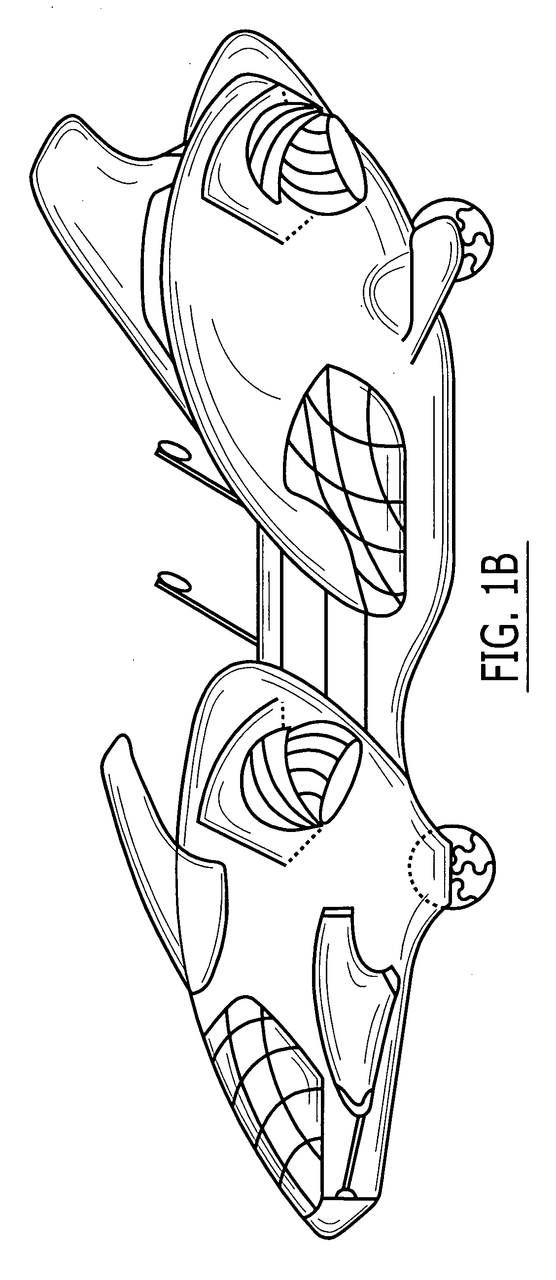
[0081]The invention will now be described by way of example with the aid of the accompanying drawings. In the images, a new and improved Vertical Take Off and Landing Lifting Body fuselage is shown in FIGS. 1A, 1B,1C, with integrated technologies of a Flying Automobile. All external structures shapes and placements are optimal for lift producing effects on a wingless aircraft, with the fuselage composed of two almost ovoidal shape sections 32, 36, 38, joined in between by a central 34 seating section. As seen from a frontal and also si...


PUM


Abstract

This apparatus is a new VTOL roadable aircraft having fore and aft sections joined by a seating midsection; with compact inlets built into its fuselage, also pairs of flight stabilizing surfaces and tail fins; the fuselage structure being a Lifting Body that provides aerodynamic lift during both forward flight and vertical descent; provided with intake chambers containing propelling surfaces rotating on longitudinal axis in opposite senses, and external pairs of swiveled nozzles producing thrust vectoring; these nozzles using conventional devices and having spins directed by original controls of corresponding identical movement directions; with standard automobile equipment integrated with the vehicle compact design and dimensions, making it compatible for road transport and enabling direct transitions to flight mode; and safe landing systems for emergencies are provided with half the technology being off the shelf devices as those in use by NASA and the US Airforce.

Description

CROSS REFERENCE TO RELATED APPLICATIONS[0001]Not Applicable.STATEMENT REGARDING FEDERALLY SPONSORED RESEARCH OR DEVELOPMENT[0002]Not Applicable.DESCRIPTION OF ATTACHED APPENDIX[0003]Not Applicable.BACKGROUND OF THE INVENTION[0004]This invention relates generally to the field of VTOL aircraft and more specifically to Roadable VTOL vehicles.[0005]For more than half a century there have been inventions and vehicles aiming to function both in the air and on roads in continuous transit from one environment to the other. Commonly known as flying cars, all have encountered major obstacles in attaining their purposes due to requiring interruptions for the removal or addition of structures specific to one operational regime such as wings, prior to entering the next functional medium. Safety was a major issue compromised because of employing externally exposed, large size propelling surfaces during road traffic. Crafts using ducted propulsion systems suffered from either oversized structures ...

Claims


Application Information

Patent Timeline
Patent Type & Authority Applications(United States)
IPC IPC(8): B64C37/00B64C29/00B62K21/12
CPCB64C29/0025Y10T74/2078B64C37/00B60F5/02
Inventor JIANU, LAURENTIU
Owner JIANU LAURENTIU
Why Eureka
Try Eureka