Device and method for inductive measurements - self test

a self-testing, inductive measurement technology, applied in the direction of instruments, base element modifications, hardware monitoring, etc., can solve the problems of inability to quantitatively check individual components, low meaning of calibration on such a sample fault, etc., to achieve high reliability of measurement results and facilitate calibration of the device.

Active Publication Date: 2010-11-25
PRUTECHNIK DIETER BUSCH AG
View PDF2 Cites 10 Cited by
  • Summary
  • Abstract
  • Description
  • Claims
  • Application Information

AI Technical Summary

Benefits of technology

[0014]In the approach in accordance with the invention, the self-test unit undertakes systematic quantitative checking of the signal processing functions of the signal processing unit, the transmitting coil arrangement, and the receiver coil arrangement, and upon request to undertake calibration of the signal processing unit with a calibration standard which is to replace the transmitter coil arrangement and / or the receiver coil arrangement. This is advantageous because it allows for comprehensive checking of the functions of the front-end, especially of the filters and amplifiers as well as the probe, and thus, high reliability of the measurement results is achieved. In particular, calibration of the device is also easily enabled. This applies especially to calibration with respect to the adjustable preamplifier.

Problems solved by technology

In particular, high reliability is achieved compared to the calibration known in the prior art on a simulated sample fault since the latter in practice generally does not emerge in the precise form of the simulated fault and thus the meaningfulness of calibration on such a sample fault is relatively low.
Further, the individual components cannot be separately quantitatively checked.

Method used


Image

  • Device and method for inductive measurements - self test
  • Device and method for inductive measurements - self test
  • Device and method for inductive measurements - self test

Examples


Embodiment Construction

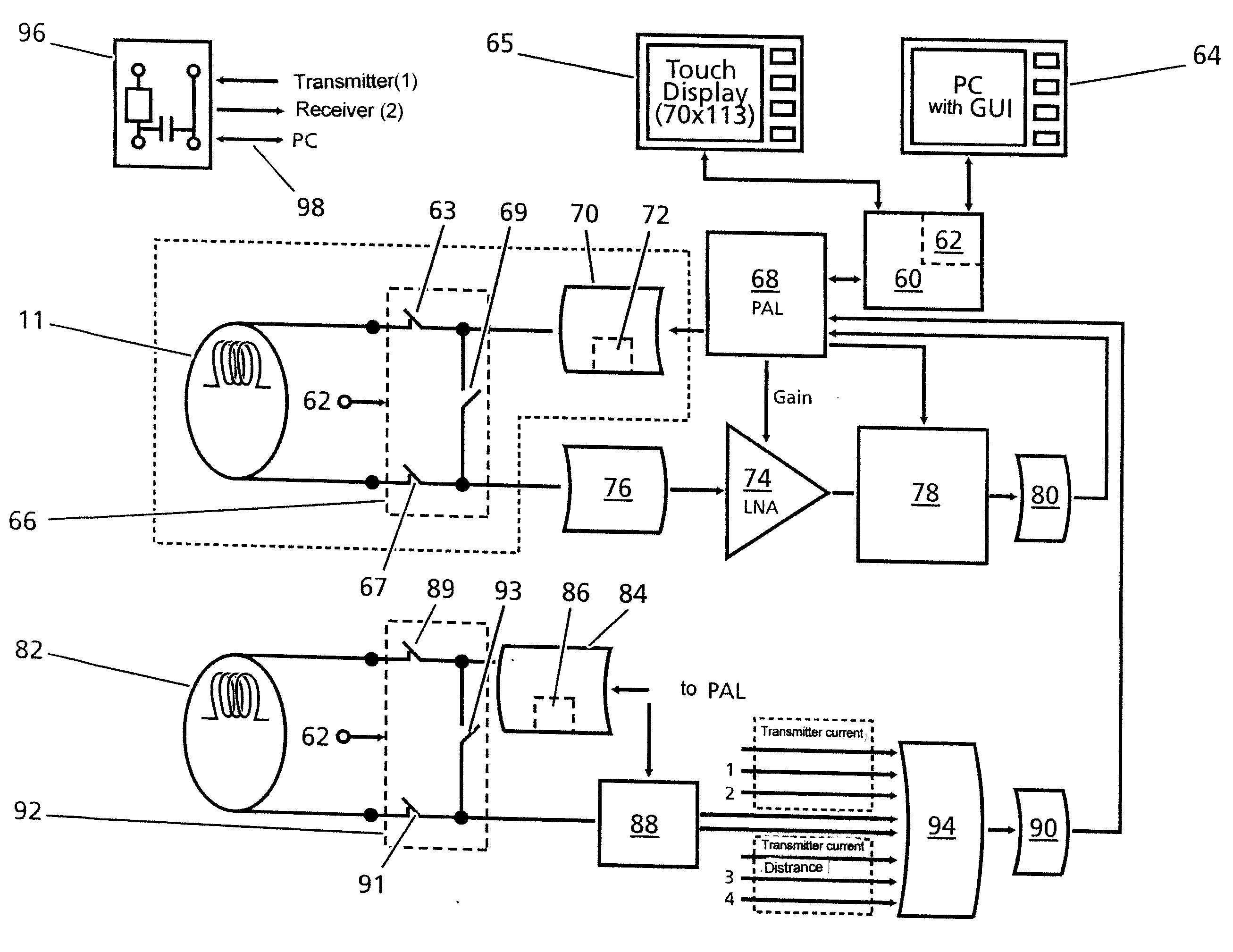
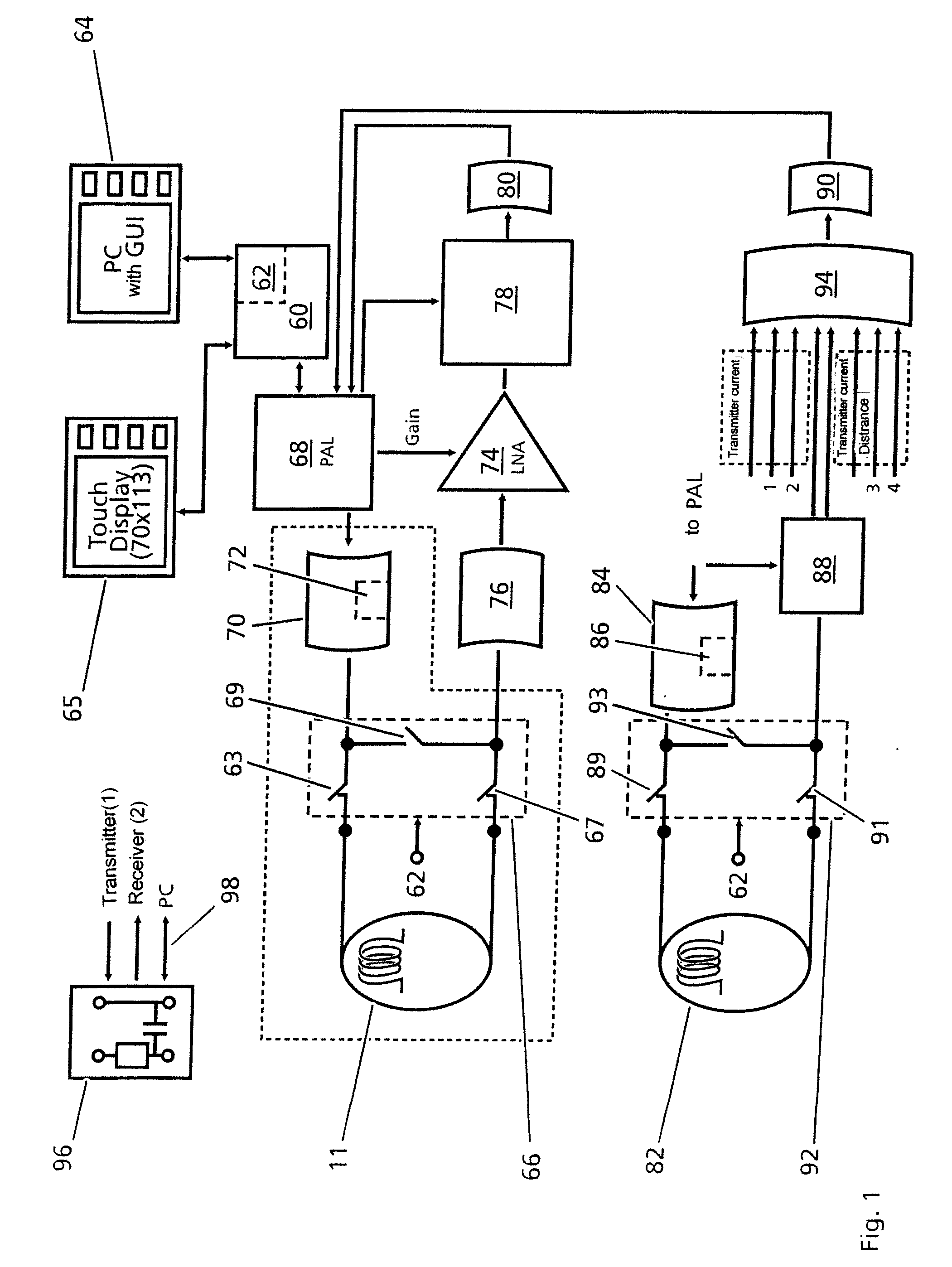
[0028]FIG. 1 shows a block diagram of an inductive measurement device with a self-test function and calibration function according to an aspect of the invention. A signal processor 60 communicates with a programmable array logic (PAL) element 68. The PAL element 68 is designed to control the A / D converter and D / A converter. The PAL element 68 also supplies a transmitter coil driver 70 which is provided with a current sensor 72, and delivers the signal for the transmitter coil arrangement (not shown in FIG. 1) of the probe 11 (i.e., measurement head). The receiver coil signal of the receiver coil arrangement (not shown in FIG. 1) of the probe 11 is provided to a low-noise amplifier 74 which is used as a preamplifier. The gain of the low-noise amplifier 74 is controlled or variably set by the processor 60 by way of the PAL element 68. The signal amplified by the amplifier 74 passes through a resonance filter 78 and is supplied to the PAL element 68 and then the processor 60 for proces...


PUM


Abstract

Method for nondestructive and noncontact detection of faults in a test piece, with a transmitter coil arrangement with at least one transmitter coil that transmits periodic electromagnetical AC fields to a test piece, a receiver coil arrangement with at least one receiver coil for detecting a periodic electrical signal having a carrier oscillation whose amplitude and/or phase is modulated by a fault in the test piece. A signal processing unit produces a useful signal from the receiver coil signal, and an evaluation unit evaluates the useful signal to detect a fault in the test piece. A self-test unit undertakes systematic quantitative checking of signal processing functions of the signal processing unit and/or of the transmitter coil arrangement and/or of the receiver coil arrangement and/or upon external request undertakes calibration of the signal processing unit using a calibration standard which replaces the transmitter coil arrangement and/or of the receiver coil arrangement.

Description

BACKGROUND OF THE INVENTION[0001]1. Field of the Invention[0002]This invention relates to a device and method for nondestructive and noncontact detection of faults in a test piece. In particular, the present invention relates to fault detection using measurements of an eddy current or magnetic flux leakage. Furthermore, the invention relates to a device and a method for detecting electrically conductive particles in a liquid flowing in a pipe segment using the eddy currents induced in the particles being detected.[0003]2. Description of Related Art[0004]Conventional nondestructive and noncontact detection of faults in a test piece of a semi-finished metallic product is performed by inducing and measuring eddy currents in the test piece. In doing so, the test piece is exposed to periodic alternating electromagnetic fields through a sinusoidally energized transmitter coil. The resulting eddy currents induced in the test piece induce a periodic electrical signal in a coil arrangement w...

Claims


Application Information

Patent Timeline
Patent Type & Authority Applications(United States)
IPC IPC(8): G01R31/00G01R27/08
CPCG01N27/9026G01R35/005G01N27/9086G01N27/9046
Inventor HOLZL, ROLAND
Owner PRUTECHNIK DIETER BUSCH AG
Why Eureka
Try Eureka