
Imaging apparatus and reproducing apparatus

a technology of reproducing apparatus and image, which is applied in the field of image processing equipment, can solve the problems of affecting the reproduction effect of video, affecting the reproduction effect, so as to maintain compatibility with existing viewing and reproduction environments

Inactive Publication Date: 2010-11-25
CANON KK
View PDF15 Cites 28 Cited by
  • Summary
  • Abstract
  • Description
  • Claims
  • Application Information

AI Technical Summary

Benefits of technology

[0015]The present invention is directed to an imaging apparatus capable of changing a frame rate in view of a photographer's intention and maintaining compatibility with existing viewing and reproduction environments.
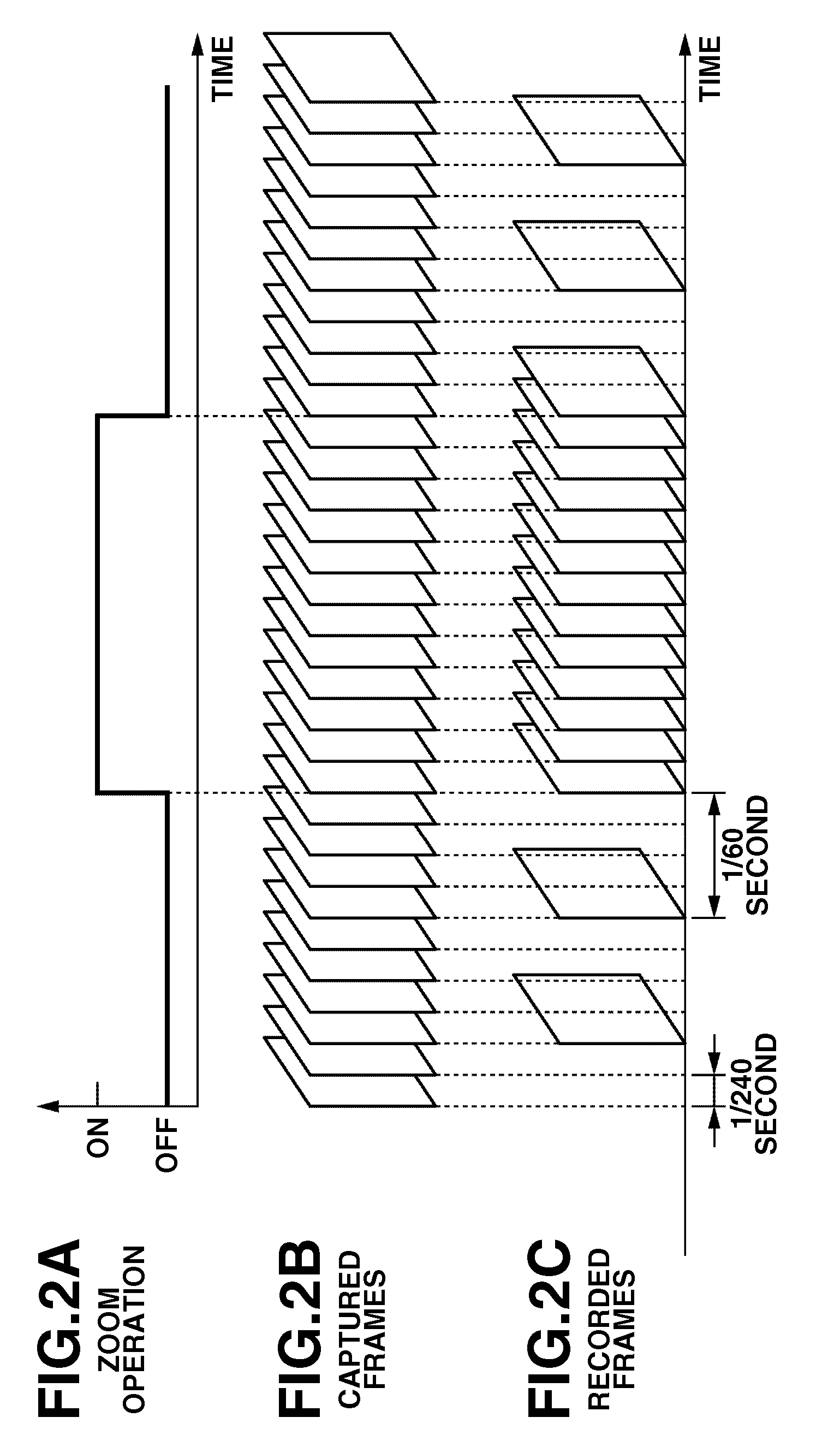
[0017]Based on an imaging apparatus and a reproducing apparatus according to the present invention, videos including zoom operations can be reproduced. Since videos are reproduced at a standard frame rate, compatibility with existing video display apparatuses can be ensured. During periods including zoom operation periods, videos are recorded at a frame rate higher than a normal frame rate, and when the videos are reproduced, the frame rate is reduced to the standard frame rate. Thus, high-quality reproduction videos can be displayed.

Problems solved by technology

However, based on the above techniques discussed in Japanese Patent Application Laid-Open No. 2003-274360 (U.S. Pat. No. 7,456,875) and Japanese Patent Application Laid-Open No. 2007-134991 (USPA 2007 / 0104462), change of the frame rate does not reflect photographer's intention.
Thus, when a video signal is input and the frame rate thereof is changed in the middle of processing, even if the change of the frame rate can be followed, the video may be displayed at an unnatural rendering speed misaligned with the actual time.
Since compatibility between these viewing and reproduction environments is not taken into consideration, use of the technique of variable frame rate recording is limited.

Method used


Image

  • Imaging apparatus and reproducing apparatus
  • Imaging apparatus and reproducing apparatus
  • Imaging apparatus and reproducing apparatus

Examples


Embodiment Construction

[0036]Various exemplary embodiments, features, and aspects of the invention will be described in detail below with reference to the drawings.

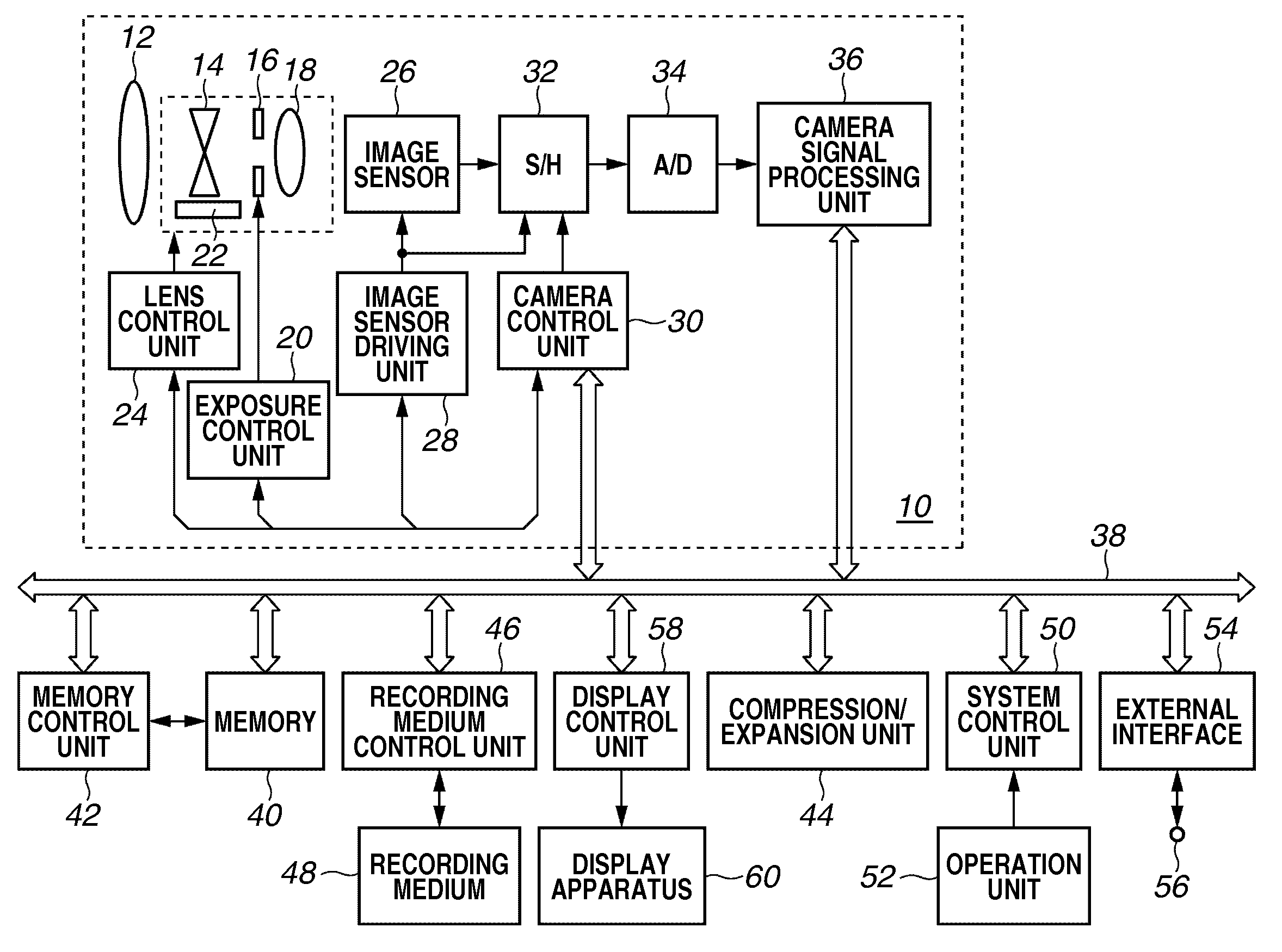
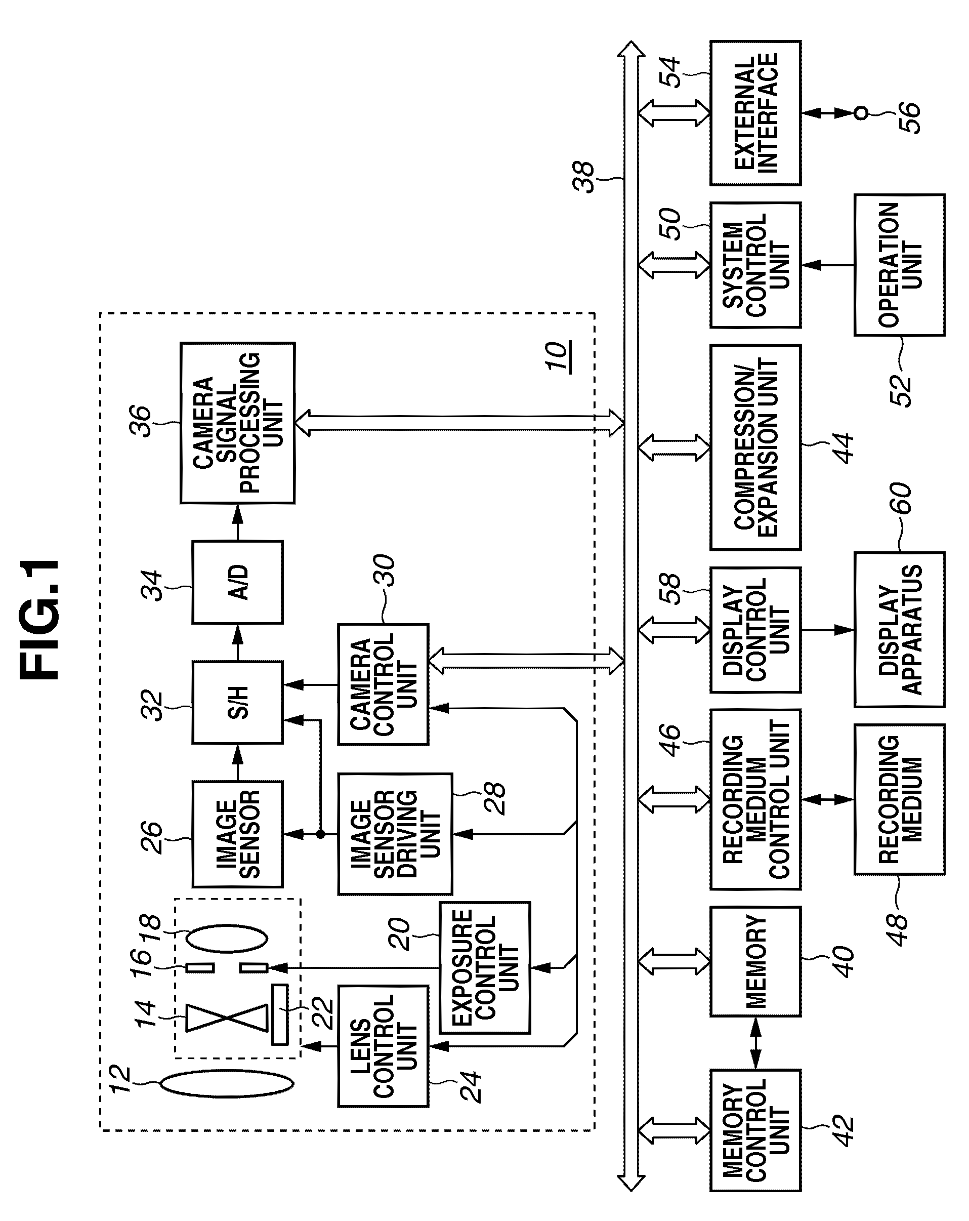
[0037]FIG. 1 is a block diagram illustrating a schematic configuration of an exemplary embodiment of the present invention. A configuration and a basic operation of the present exemplary embodiment will be described with reference to FIG. 1.

[0038]An imaging unit 10 (camera unit) has the following configuration and functions. The imaging optical system of the imaging unit 10 includes a front lens 12, a zoom lens 14, a diaphragm 16, and a focus lens 18. The front lens 12 is fixed to a lens barrel, and the zoom lens 14 and the focus lens 18 can move along the optical axis. The diaphragm 16 is arranged between the zoom lens 14 and the focus lens 18.

[0039]An exposure control unit 20 receives a control signal from a camera control unit 30 and controls the aperture of the diaphragm 16 based on the control signal. A zoom position sensor 22 detects the ...


PUM


Abstract

An imaging unit outputs a video signal at a frame rate higher than a standard frame rate. During a zoom operation period or a period including the zoom operation period and periods before and after the zoom operation, a video signal from the imaging unit is recorded in a recording medium at a high recording frame rate. Other than this period, a video signal is recorded in the recording medium at the standard frame rate. The recording frame rate and zoom operation information is recorded as metadata in the recording medium. During reproduction, based on a set reproduction mode, thinning processing is carried out on a video signal recorded during a zoom operation, and the processed signal is output at the standard frame rate. In this way, it is possible to change a frame rate in view of a photographer's intention and assure compatibility with existing viewing and reproduction environments.

Description

BACKGROUND OF THE INVENTION[0001]1. Field of the Invention[0002]The present invention relates to an imaging apparatus that records moving images, and to a reproducing apparatus that reproduces the moving images, such as a video camera or a digital camera.[0003]2. Description of the Related Art[0004]In recent years, a recording and reproducing apparatus capable of recording / reproducing high-quality video signals such as high definition (HD) video signals or HD signals, and a video display apparatus capable of displaying such signals as images have been widely spread. Background techniques of an image processing system used in these apparatuses include techniques of miniaturizing the size of an image sensor, increasing the number of pixels, increasing the speed of transfer processing, and improving the efficiency of coding such as the H.264 standard. In addition, various types of video display apparatuses have been made available, such as those of a liquid crystal type, a plasma type,...

Claims


Application Information

Patent Timeline
IPC IPC(8): H04N5/262
CPCH04N5/232H04N5/23296H04N5/2621H04N5/765H04N5/772H04N5/781H04N9/87H04N5/85H04N5/907H04N9/7921H04N9/8042H04N9/8063H04N9/8205H04N5/783H04N23/633H04N23/69
Inventor SUZUKI, TOSHIHIKO
Owner CANON KK
Learn More