
Micro passage cold plate device for a liquid cooling radiator

a cold plate device and liquid cooling technology, applied in the direction of semiconductor/solid-state device details, electrical equipment construction details, instruments, etc., can solve the problems of difficult liquid cooling, high cost, and uneven temperature of the electric core chip contacting the cold plate, so as to reduce the integral thermal resistance of the cold plate, reduce the flow resistance of the working medium, and increase the capillary attraction

Inactive Publication Date: 2010-11-25
BEIJING AVC TECH RES CENT
View PDF48 Cites 14 Cited by
  • Summary
  • Abstract
  • Description
  • Claims
  • Application Information

AI Technical Summary

Benefits of technology

"The present invention provides a micro passage cold plate for a liquid cooling radiator that can evenly distribute temperature, have better heat dissipation performance, and enhance the stability of the flow of the two-phase flow working medium. The cold plate has a trumpet-shaped inlet and outlet, a liquid storage zone with a nozzle structure, a micro passage zone with a long distance from the heating area of the core chip, and a vapor discharge zone with a straight through structure. The nozzle structure helps the working medium enter the micro passage zone with the greatest flow velocity, resisting the unstable phenomenon resulting from the vapor flowing backward. The longer micro passage zone also helps stabilizing the movement of the vapor and reduces the capillary attraction. The working medium changes the state thereof to the vapor from the liquid with vaporizing latent heat and the temperature of the working medium little increases, apparently decreasing the integral thermal resistance of the cold plate."

Problems solved by technology

However, due to the limitation of the material of the cold plate, the thermal resistance being incapable of lowering further with respect to higher absorbed temperature of the liquid, and a high temperature gradient in the cold plate, it results in the electronic core chip contacting the cold plate providing the temperature unevenly.
Besides, the driving force for the liquid is constant with the thermal resistance of the liquid being unchanged is unable to satisfy the heat dissipation need of the future electronic core chip.
Especially, it is hard for the liquid to cool the heat spots effectively, the high heat flex leads noise from the fan, and the life span of the pump meets a great challenge.
But, it has been long time that no proper design for the liquid cooling radiator is developed.

Method used


Image

  • Micro passage cold plate device for a liquid cooling radiator
  • Micro passage cold plate device for a liquid cooling radiator
  • Micro passage cold plate device for a liquid cooling radiator

Examples


first embodiment

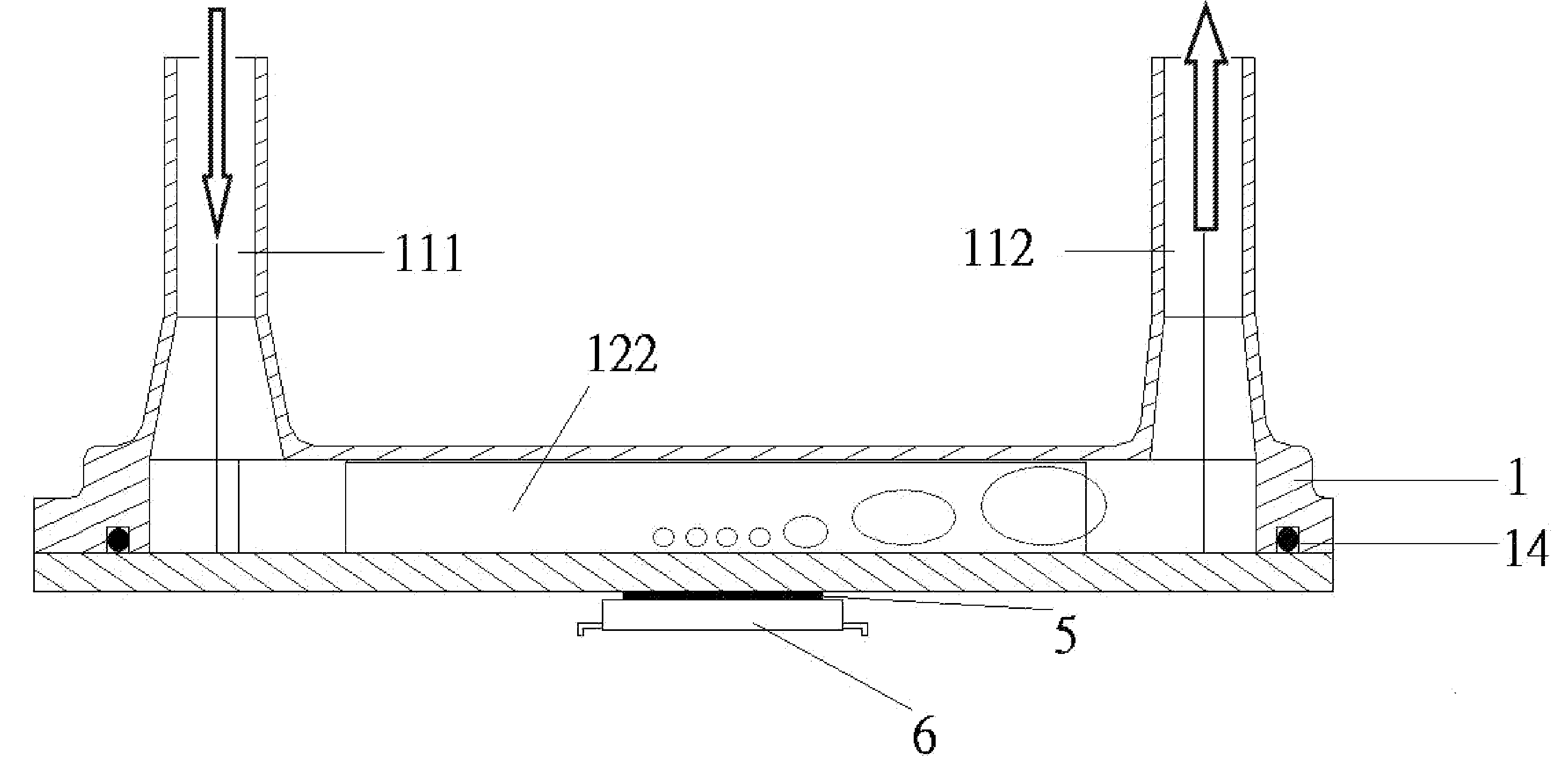
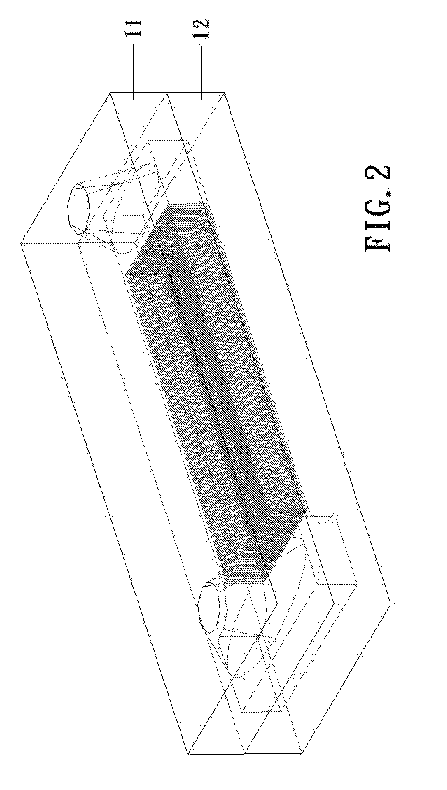
[0038]Referring to FIGS. 3A, 3B, 3C and 3D, the cold plate structure for a liquid cooling radiator according to the present invention provide a lower plate 12 made of silicon and the upper cover 11 is made of silicon or quartz. The lower plate 12 is bonded to the upper cover 11 as a single piece. The upper cover 11 is formed with the trumpet-shaped inlet 111 and outlet 112 by means of the quartz being treated with the isotropic wet etching. The trumpet-shaped inlet 111 and outlet 112 are flush with the top surface of the upper cover 11. Further, the lower plate 12 is disposed with a liquid storage zone 121 next to the inlet 111 and a vapor discharge zone 123 next to the outlet 112. A micro passage zone 122 is disposed between the liquid storage zone 121 and the vapor discharge zone 123 to communicate with the liquid storage zone 121 and the vapor discharge zone 123. The liquid storage zone 121 and the vapor discharge zone 123 are provided a chamber respectively. The micro passage zo...

second embodiment

[0040]Referring to FIGS. 5A, 5B, 5C and 5D, the cold plate for a liquid cooling radiator according to the present invention is illustrated. The lower plate 12 is made of a metal such as copper or aluminum, and the upper cover 11 is made of a metal the same as the lower plate 12 or different from the lower plate 12. The upper cover 11 is joined to the lower plate 12 with brazing in case of the upper cover 11 and the lower plate being made of the identical metal. The upper cover 11 is joined to the lower plate 12 with soldering in case of the upper cover 11 and the lower plate being made of different metals. The upper cover 11 is fabricated with the computer numerical control (CNC) machine, the die casting machine or the metal injection module machine to work the trumpet-shaped inlet 111 and outlet 112, the liquid storage zone 121 with the nozzle structure and the vapor discharge zone 123 with straight through structure. The lower plate 12 shown in FIG. 5A is specifically illustrated ...

third embodiment

[0041]Referring to FIGS. 7A, 7B, 7C and 7D, the micro passage for a liquid cooling radiator according to the present invention is illustrated. The lower plate 12 is made of a metal such as copper or aluminum and the upper cover 11 is made of a metal or plastics. The lower plate 12 is attached to the upper cover 12 tightly with screws 13, and, in order to seal the cold plate tightly, an O-ring seal 14 is disposed between the upper cover 11 and the lower plate 12. The trumpet-shaped inlet 111 and outlet 112 extend outward the top surface of the upper cover 11. The upper cover 111 can be fabricated by means of the plastics injection mold or the metal injection module such that the trumpet-shaped inlet 111 and outlet 112, the liquid storage zone 121 with the nozzle structure, the vapor discharge zone 123 with straight through structure, the micro passage zone and the groove 113 for receiving the O-ring seal 14 can be formed properly. The lower plate 12 shown in FIG. 7A is illustrated sp...


PUM


Abstract

A micro passage cold plate device for a liquid cooling radiator includes a upper cover and a lower plate. The upper cover has a working medium inlet at a side thereof and a working medium outlet at another side thereof. The inlet and outlet are trumpet-shaped such that the working medium expansively enters the cold plate gradually and leaves the cold plate with a reduced way gradually. Hence, the cold plate provides an even distribution of temperature, a lower thermal resistance and a better heat dissipation performance such that the stability of the two-state flow of the working medium is enhanced for heat dissipation device in the field of electronic field.

Description

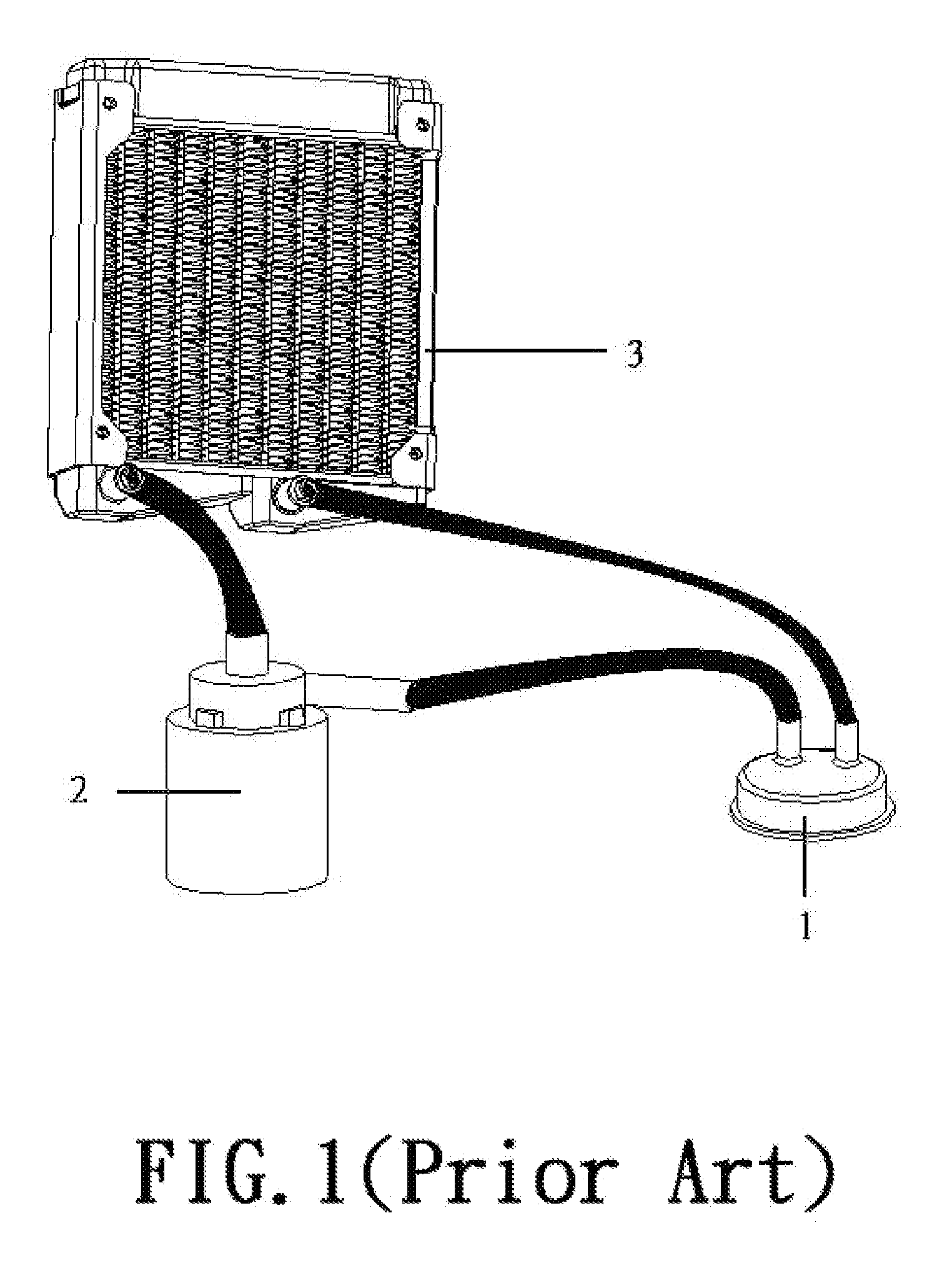
BACKGROUND OF THE INVENTION[0001]1. Field of the Invention[0002]The present invention is related to a heat dissipation device in the field of electronic products and particularly to a liquid cooling heat dissipation device with phase change of the working medium between the liquid and vapor.[0003]2. Brief Description of the Related Art[0004]Currently, the heat dissipation for the high performance electronic products mostly is employed with the liquid cooling type device. Referring to FIG. 1, the conventional liquid cooling device comprises a cold plate 1, a pump 2, a fin radiator 3 and a soft hose connecting with the previous parts. The cold plate 1 contacts the heat source, which is the electronic core chip such as the CPU, and the pump 2 drives the liquid to pass through the cold plate 1 and absorb the heat. The heat is released to the open air by means of the fin radiator 3 and the cooled liquid returns to pass through the cold plate 1. The preceding operation is cycled again and...

Claims


Application Information

Patent Timeline
Patent Type & Authority Applications(United States)
IPC IPC(8): H05K7/20
CPCG06F1/20H01L23/427H01L23/473H01L2924/0002H01L2924/00
Inventor LI, JI
Owner BEIJING AVC TECH RES CENT
Learn More