Visualization of 3D images in combination with 2d projection images

a visualization and 3d technology, applied in the field of digital image processing, can solve the problems of deteriorating 2d projection datasets, scattered x-rays, etc., and achieve the effects of detailed and structured visualization of the vessel tree, and improving the visibility of the final combined 3d/2d images

Inactive Publication Date: 2010-11-25
KONINKLIJKE PHILIPS ELECTRONICS NV
View PDF16 Cites 28 Cited by
  • Summary
  • Abstract
  • Description
  • Claims
  • Application Information

AI Technical Summary

Benefits of technology

[0041]According to a further embodiment of the invention the method further comprises a segmentation of the 3D representation in relevant regions, which are supposed to be displayed, and non-relevant regions, which are supposed not to be displayed. This may provide the advantage that a very detailed and structured visualization of the vessel tree of a patient under examination can be obtained. Thereby, regions of the pat...

Problems solved by technology

A) Reconstruction artifacts: These artifacts are typically related to beam hardening effects and scatter problems.
Scatter problems are caused because an X-ray absorbing material always also represents a material causing an un...

Method used


Image

  • Visualization of 3D images in combination with 2d projection images
  • Visualization of 3D images in combination with 2d projection images
  • Visualization of 3D images in combination with 2d projection images

Examples


Embodiment Construction

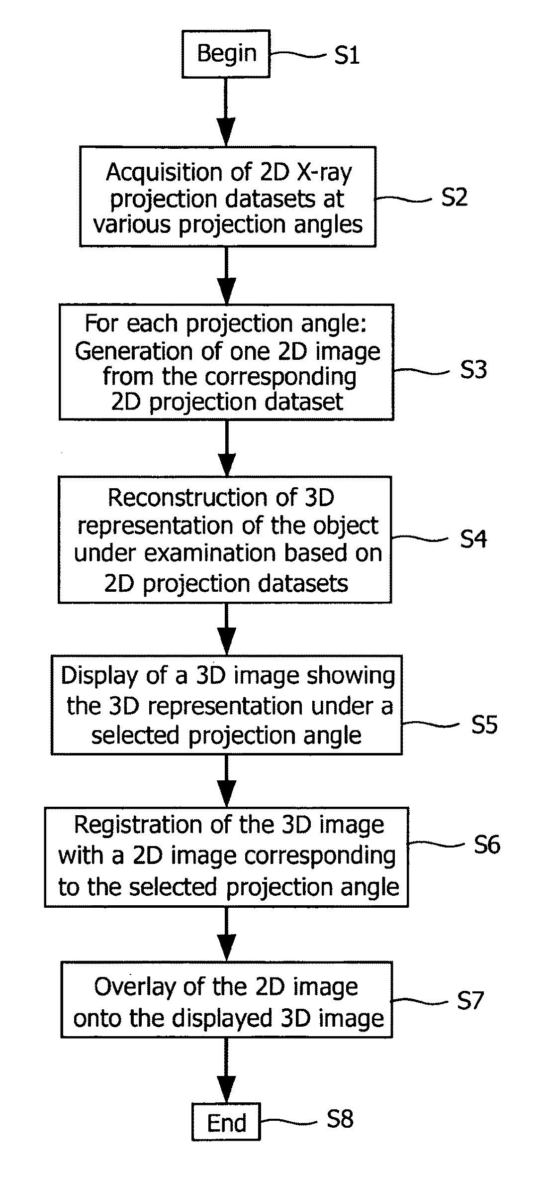
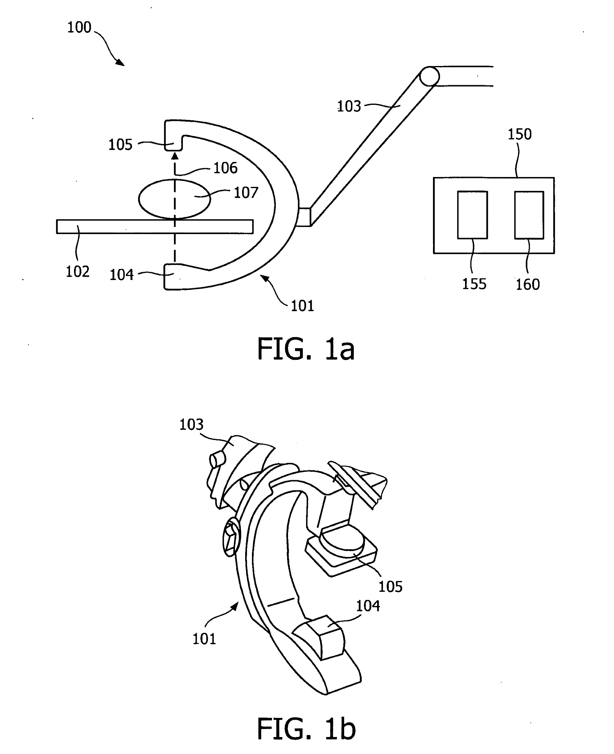
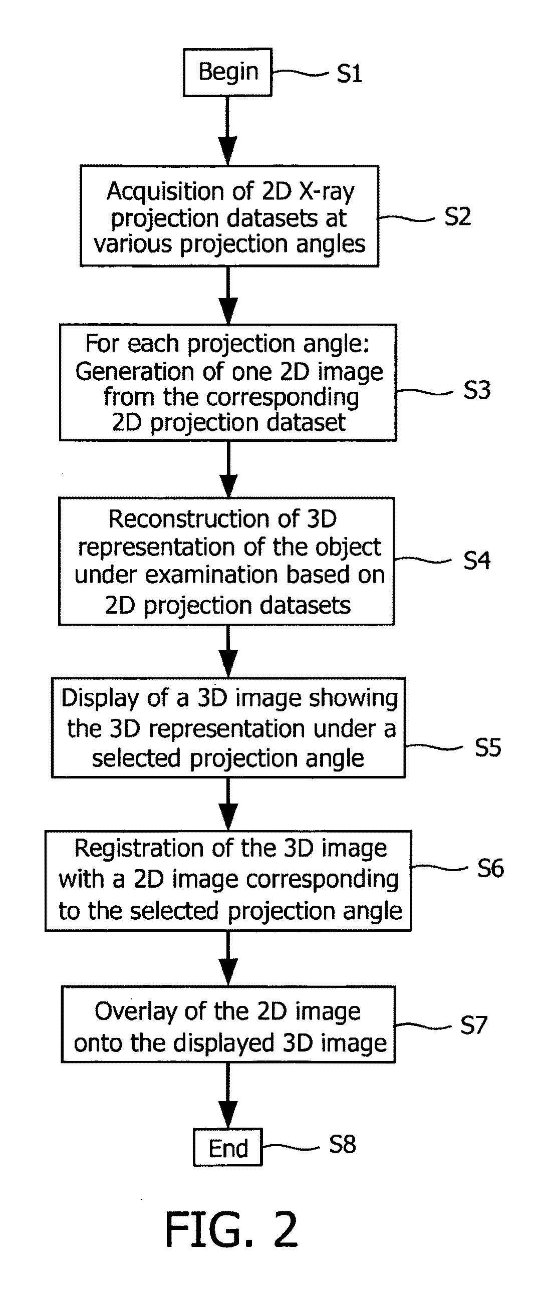
[0060]The illustration in the drawing is schematically. It is noted that in different figures, similar or identical elements are provided with the same reference signs or with reference signs, which are different from the corresponding reference signs only within the first digit.

[0061]Referring to FIGS. 1a and 1b of the drawing, a medical X-ray imaging system 100 according to an embodiment of the invention comprises a swing arm scanning system (C-arm) 101 supported proximal a patient table 102 by a robotic arm 103. Housed within the swing arm 101, there is provided an X-ray tube 104 and an X-ray detector 105. The X-ray detector 105 is arranged and configured to receive X-rays 106, which have passed through a patient 107 representing the object under examination. Further, the X-ray detector 105 is adapted to generate an electrical signal representative of the intensity distribution thereof. By moving the swing arm 101, the X-ray tube 104 and the detector 105 can be placed at any desi...


PUM


Abstract

It is described an improved visualization of an object under examination (107). Thereby, original 2D rotational projections are combined preferably in an overlaying manner with corresponding viewings of a 3D reconstruction. By showing the 2D rotational projections in combination with the 3D reconstruction, 3D vessel information can be compared with the original 2D rotational image information over different rotational angles. In a clinical setup the combined visualization will allow for an easy check if findings in the 3D RA volume such as stenosis or aneurysms are not overestimated or underestimated due to e.g. an incomplete filling with contrast agent and/or a spectral beam hardening during the rotational scan.

Description

FIELD OF INVENTION[0001]The present invention generally relates to the field of digital image processing, in particular for medical purposes in order to enhance the visualization of acquired projection datasets of an object under examination. In particular, the present invention relates to the segmentation and visualization of rotational angiographic information, which are obtained by means of three-dimensional rotational angiography (3D RA), which is very useful for interventional radiology, especially in the field of endovascular therapy.[0002]Specifically, the present invention relates to a method for displaying images of an object under examination, wherein a series of two-dimensional (2D) projection datasets of the object under examination is acquired at various projection angles and a three-dimensional (3D) representation of the object under examination is reconstructed based on the acquired 2D projection datasets.[0003]Further, the present invention relates to a data processi...

Claims


Application Information

Patent Timeline
IPC IPC(8): H05G1/64G06T17/00A61B6/03G06T15/08
CPCA61B6/032A61B6/4441A61B6/481A61B6/504A61B6/5235G06T2219/2012G06T15/08G06T19/20G06T2210/41G06T2219/2004G06T11/008
Inventor MIELEKAMP, PIETER MARIAHOMAN, ROBERT JOHANNES FREDERIK
Owner KONINKLIJKE PHILIPS ELECTRONICS NV
Why Eureka
Try Eureka