Method for repairing a component by coating

Inactive Publication Date: 2010-11-25
SIEMENS AG
View PDF10 Cites 9 Cited by
  • Summary
  • Abstract
  • Description
  • Claims
  • Application Information

AI Technical Summary

Benefits of technology

[0006]This is where the invention becomes relevant; the component is conditioned better for reuse than in the prior art since, after the repair, not only does the applied material have the required material composition of the component, but also the coating material deliberately has a concentration of this specific microstructural proportion which is higher than necessary for the component. During the subsequent heating of the component, which results from a targeted heat treatment or else from using the component under thermal loading, the different concentrations of the specific microstructural proportion in the repair coating and also the underlying component are adjusted in a manner governed by diffusion, such that the entire component advantageously at least approximately has the required concentration of the specific microstructural proportion again. This makes it possible to restore the properties of the component such that it is approximately comparable to the new part, and so the repaired component is also expected to have a service life comparable to that of the new component.
[0019]It is also advantageous if the component is heated to a temperature above the operating temperatures of the microstructure of the region near the surface. In this temperature range, it is always possible for the specific microstructural proportions to diffuse from the repair layer into the regions near the surface of the component. Above the operating temperatures, this process is advantageously sped up further, and this advantageously shortens the heat treatment times for subsequent treatment. The heat treatment can normally be carried out at a higher temperature level than is possible during the operation of the component, because this process acts only for a limited time on the component and can additionally be monitored more effectively, such that a safety margin to temperatures at which the integrity of the component microstructure is at risk can be chosen to be smaller than during the operation of said component.

Problems solved by technology

Therefore, the process is used in the case of components such as turbine blades which have reached the end of their service life and, in addition to visible wear phenomena such as abrasive wear or the formation of cracks, also have wear phenomena which are initially invisible, such as degradation of the microstructural regions near the surface.
In this context, it should be taken into consideration that the coating is accompanied by considerable mechanical loading and heating of the layer material, and therefore it is feared that sensitive layer materials would suffer premature degradation which reduces or prevents the subsequent effect of a balancing of the concentration of the specific microstructural proportion in the repaired component.
Mention should be made, in particular, of metals which are at great risk from oxidation and, without the measure of a casing, could merely be processed in a protective gas atmosphere, and this would make the use of cold spraying much more expensive.

Method used


Image

  • Method for repairing a component by coating
  • Method for repairing a component by coating

Examples


Embodiment Construction

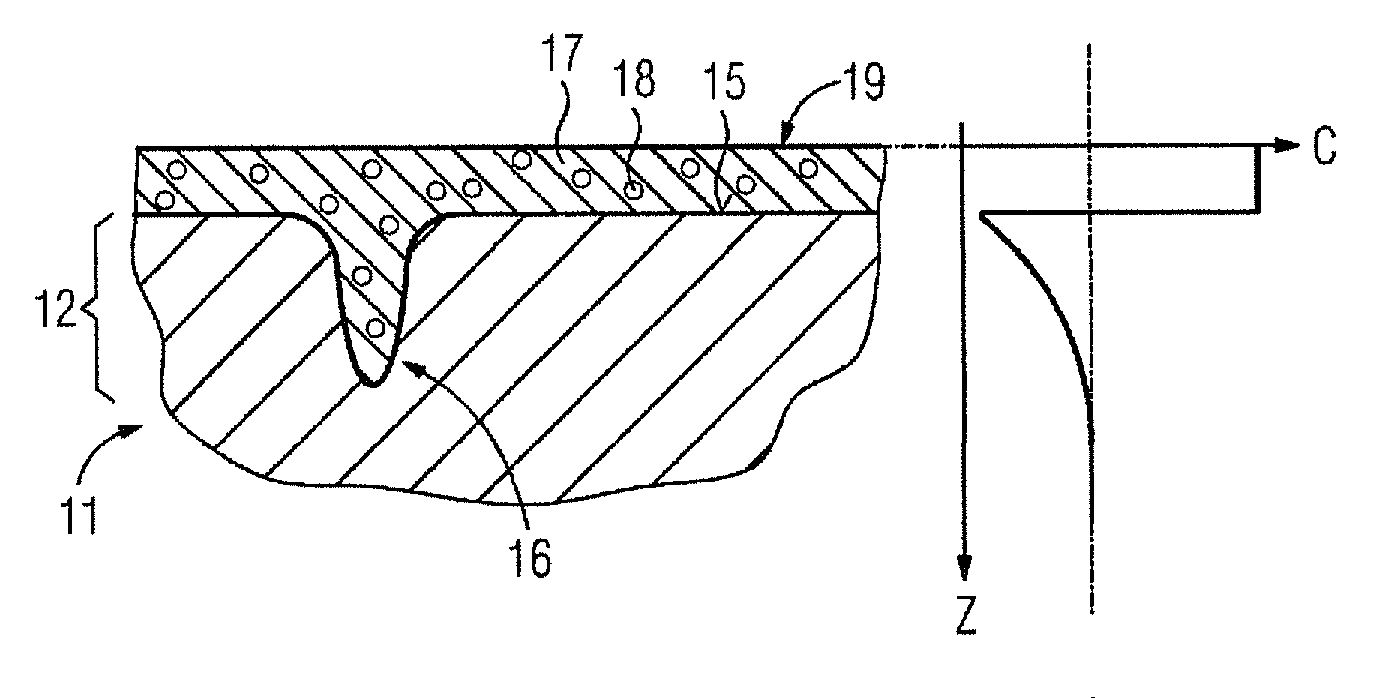
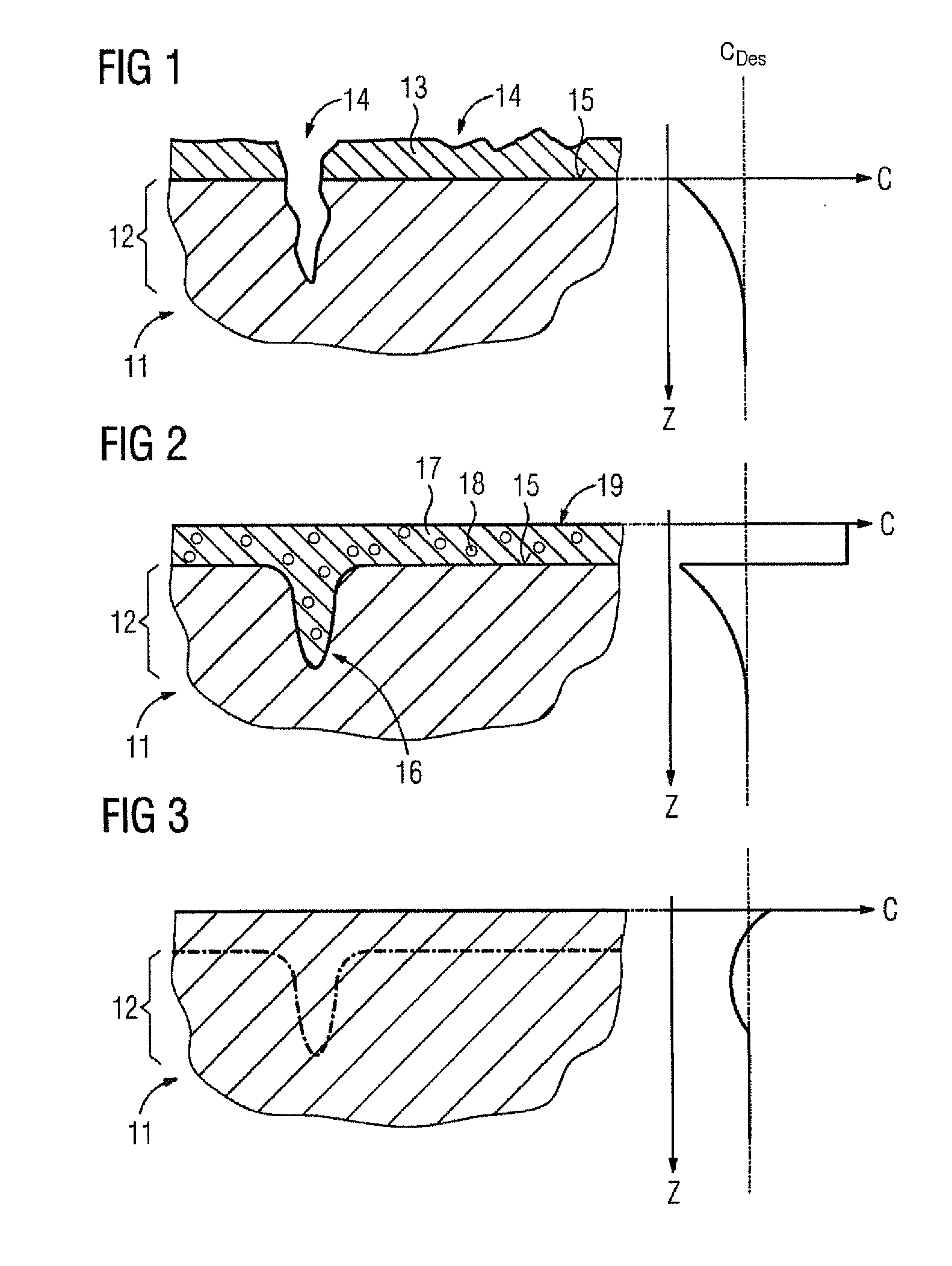
[0022]A component 11 as shown in FIG. 1 is a turbine blade formed by an MCrAlY alloy. The figure shows a region 12 near the surface of the turbine blade which has a coating 13. By way of example, this may consist of a thermal barrier coating (TBC), this layer serving to thermally protect the turbine blade. The region 12 near the surface of the component 11 can itself represent a layer on a base body (not shown in more detail), it also being possible to produce the blade in solid form from the MCrAlY alloy.

[0023]FIG. 1 also shows damaged locations 14 which may consist, for example, in abrasive wear on the surface or a crack. In addition, a graph which is true to scale with respect to the illustration of the component 11 plots the concentration of a specific microstructural proportion C against a path coordinate z which indicates the distance to the surface 15 of the uncoated component 11. By way of example, the specific microstructural proportion may be the aluminum content of the MC...


PUM

PropertyMeasurementUnit
Temperatureaaaaaaaaaa
Concentrationaaaaaaaaaa
Microstructureaaaaaaaaaa

Abstract

A method for repairing a component such as a turbine blade is provided. At the end of its operating time, the component has, for example, a depletion of aluminium in a region near the surface. The application of a repair layer is provided including particles with an increased proportion of aluminium. A subsequent heat treatment may achieve the effect of equalizing the concentration of aluminium between the repair layer and the region near the surface, and so the aluminium content required for new components is achieved again.

Description

CROSS REFERENCE TO RELATED APPLICATIONS[0001]This application is the US National Stage of International Application No. PCT / EP2008 / 062510, filed Sep. 19, 2008 and claims the benefit thereof The International Application claims the benefits of German application No. 10 2007 046 386.5 DE filed Sep. 21, 2007. All of the applications are incorporated by reference herein in their entirety.FIELD OF INVENTION[0002]The invention relates to a process for repairing a component, the region of which near the surface has damaged locations, in which process a coating material is applied to the component, in particular by cold spraying, in the form of particles, and the component is then heated.BACKGROUND OF INVENTION[0003]A process of this type is known, for example, from US 2006 / 0045785 A1. In this process, cold spraying is used to repair worn regions of a turbine blade by renewed application of material. For this purpose, the blade which comprises a titanium alloy has material comprising either...

Claims


Application Information

Patent Timeline
IPC IPC(8): C23C30/00
CPCB22F5/04B22F7/08B23P6/007B23P6/045C23C24/04C23C30/00F05D2300/2112F05C2201/0463F05C2201/0466F05D2230/40F05D2300/121F05D2300/132F05D2300/2118F01D5/005
Inventor JENSEN, JENS DAHLKLINGEMANN, JENSKRUGER, URSUSKORTVELYESSY, DANIELLUTHEN, VOLKMARREICHE, RALPHSTIER, OLIVER
Owner SIEMENS AG
Why Eureka
Try Eureka