Melt-solidified substance, copper alloy for melt-solidification and method of manufacturing the same

a technology of meltsolidification and solidified substances, which is applied in the direction of resistance welding apparatus, arc welding apparatus, reciprocating piston engines, etc., can solve the problems of structural impairing ductility, the above problem cannot be avoided, and the mechanical properties of the welded area deteriorate, so as to improve the corrosion resistance remarkably, improve the corrosion resistance, and improve the corrosion resistance

Active Publication Date: 2010-11-25
MITSUBISHI SHINDOH CO LTD
View PDF21 Cites 33 Cited by
  • Summary
  • Abstract
  • Description
  • Claims
  • Application Information

AI Technical Summary

Benefits of technology

[0006]An advantage of the present invention is to provide a melt-solidified substance such as highly practical welded substance or the like by making the strength, corrosion resistance or the like of the melt-solidified parts such as welded areas or the like excellent while the above problems are not caused. Another advantage is to provide a copper alloy for melt-solidification including materials to be welded, material to be fused, filler metal (welding rod), thermal spraying material, from which the above melt-solidified substance can be obtained easily, and a method of manufacturing the copper alloy for melt-solidification.
[0007]In order to achieve the above advantages, the invention proposes the following melt-solidified substance (welded pipe, welded structure, thermal sprayed structure, built-up structure, fused substance or the like), copper alloy for melt-solidification (materials to be welded, material to be fused, welding rod, welding line, thermal spraying material or the like), which is used to manufacture the melt-solidified substance, method of manufacturing the copper alloy (particularly, casting method).
[0008]That is, the invention is a melt-solidified substance including melt-solidified parts formed by welding, build-up welding, thermal spraying or fusing and proposes the following first to eighteenth melt-solidified substances. Meanwhile, the build-up welding and thermal spraying include a lining process.
[0009]In the first melt-solidified substance, the melt-solidified part has an alloy composition containing Zr: 0.0005 to 0.05 mass % (preferably 0.002 to 0.039 mass %, more preferably 0.003 to 0.029 mass %, further more preferably 0.004 to 0.024 mass %, and optimally 0.006 to 0.019 mass %); P: 0.01 to 0.35 mass % (preferably 0.02 to 0.19 mass %, more preferably 0.03 to 0.16 mass %, and optimally 0.035 to 0.12 mass %); and Cu: the remainder, and satisfies the following conditions (1) and (6). It is preferable that the melt-solidified part of the first melt-solidified substance satisfy the following conditions (7), (10), and (11) in addition to the above conditions.
[0010]In the second melt-solidified substance, the melt-solidified part has an alloy composition containing Zr: 0.0005 to 0.05 mass % (preferably 0.002 to 0.039 mass %, more preferably 0.003 to 0.029 mass %, further more preferably 0.004 to 0.024 mass %, and optimally 0.006 to 0.019 mass %); P: 0.01 to 0.35 mass % (preferably 0.02 to 0.19 mass %, more preferably 0.03 to 0.16 mass %, and optimally 0.035 to 0.12 mass %); Zn: 0.01 to 38 mass % (preferably 5 to 37 mass %, more preferably 12 to 36 mass %, and optimally 17 to 34 mass %); and Cu: the remainder, and satisfies the following conditions (1) and (6). It is preferable that the melt-solidified part of the second melt-solidified substance satisfy the following conditions (2) to (5), and (7) to (12) in addition to the above conditions.
[0011]In the third melt-solidified substance, the melt-solidified part has an alloy composition containing Zr: 0.0005 to 0.05 mass % (preferably 0.002 to 0.039 mass %, more preferably 0.003 to 0.029 mass %, further more preferably 0.004 to 0.024 mass %, and optimally 0.006 to 0.019 mass %); P: 0.01 to 0.35 mass % (preferably 0.02 to 0.19 mass %, more preferably 0.03 to 0.16 mass %, and optimally 0.035 to 0.12 mass %); one or more elements selected from Sn: 0.01 to 15 mass % (preferably 0.1 to 12 mass %, more preferably 0.5 to 8 mass %, and optimally 0.6 to 2 mass %), Si: 0.01 to 5 mass % (preferably 0.05 to 4.8 mass %, more preferably 0.1 to 4.5 mass %, and optimally 2.6 to 3.7 mass %), and Al: 0.01 to 9 mass % (preferably 0.1 to 8.5 mass %, and more preferably 0.2 to 3 mass %); and Cu: the remainder, and satisfies the following conditions (1) and (6). It is preferable that the melt-solidified part of the third melt-solidified substance satisfy the following conditions (2) to (5), and (7) to (12) in addition to the above conditions.

Problems solved by technology

In a welded substance such as copper alloy welded pipe or the like, it is common that the metallic structure transforms from fine recrystallized structure to cast structure by melting, therefore the mechanical properties in the welded areas deteriorate.
Since the copper alloys disclosed in Patent Documents 1 and 2 rarely have the effect to suppress the grain coarsening in the welded areas, the above problem cannot be avoidable.
Meanwhile, the strength such as tensile strength, proof stress, fatigue strength or the like considerably depends on the grain size (Hall-Petch Effect), and the coarsening of the metallic structure impairs the ductility.
Likewise, the corrosion resistance also deteriorates.
What is worse is, since the fine recrystallized structure exists nearby, for example, if stress is applied to the copper alloy, the stress is centralized on the weaker areas, and then the copper alloy becomes more vulnerable.
As a result, the copper alloy can be fractured or deformed even by small stress.
Similarly, with respect to the corrosion resistance, since the fine recrystallized structure exists nearby, it becomes more likely that the welded areas corrode selectively.
However, the former cannot solve the problem in terms of the strength or corrosion resistance since such a high strength material is not always available.
Meanwhile, the latter has problems in terms of the manufacturing cost and facilities.
Another huge problem in the welded substance is the soundness of the welded area.
These defects are mainly caused by the growth of dendrite, same as a casting product.

Method used


Image

  • Melt-solidified substance, copper alloy for melt-solidification and method of manufacturing the same
  • Melt-solidified substance, copper alloy for melt-solidification and method of manufacturing the same
  • Melt-solidified substance, copper alloy for melt-solidification and method of manufacturing the same

Examples


Embodiment Construction

[0111]As an embodiment, melt-solidified substances according to the present invention Nos. 1 to 67 illustrated in Tables 1 to 4 are manufactured.

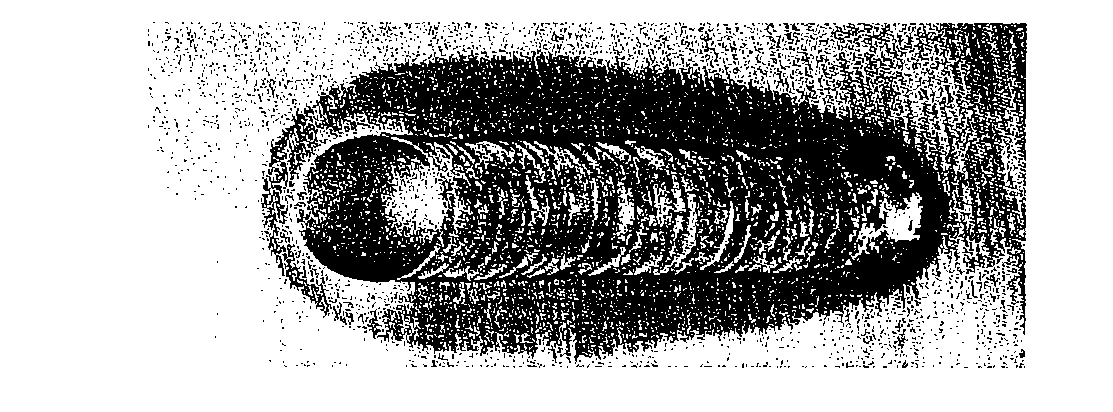
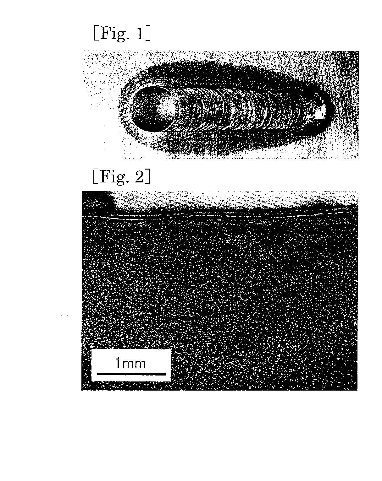
[0112]Each of the melt-solidified substances Nos. 1 to 43 is obtained by forming a bead A, a melt-solidified part, on the surface of a copper alloy plate A1 with a TIG welder. That is, the bead A (melt-solidified part) is formed on the copper alloy plate A1 to have a welding pool (welded area) of about 3 mm in depth with the bead of about 8 mm in width by moving an electrode for about 40 mm in the across-the-width direction of the plate at the welding current: 150 A (varying from 140 to 180 A depending on a material) and the moving speed: 100 mm / min, while the electrode is kept 1 to 2 mm apart from the copper alloy plate A1. Meanwhile, in determining the welding current, top priority is given to obtain the welding pool as large as described above. The copper alloy plates A1 are the copper alloys for melt-solidification according to the inve...


PUM

PropertyMeasurementUnit
grain sizeaaaaaaaaaa
mass %aaaaaaaaaa
mass %aaaaaaaaaa

Abstract

A melt-solidified substance includes melt-solidified portions formed by welding, build-up spray welding, metallizing or fusing. The melt-solidified portions have the alloy composition containing Zr: 0.0005 to 0.05 mass %, P: 0.01 to 0.34 mass %, Cu: the remainder and satisfying the relationship between the contents of P and Zr, [P] / [Zr]=0.3 to 20, and the mean grain size in the macrostructure after melt-solidification is 300 μm or less. If Fe and / or Ni are contained in the melt-solidified portion as inevitable impurities, the content of Fe or Ni is restricted to be 0.3 mass % or less when either Fe or Ni is contained, and the total content of Fe and Ni is restricted to be 0.4 mass % or less when both Fe and Ni are contained.

Description

TECHNICAL FIELD[0001]The present invention relates to a melt-solidified substance including melt-solidified parts including welded part, built-up part, thermal sprayed layer, fused end part of copper alloy formed by melt-solidification including welding, build-up welding, thermal spraying, fusing, a copper alloy for melt-solidification used to form the above melt-solidified parts including material to be welded, material to be fused, filler metal (welding rod), thermal spraying material, and a method of manufacturing the same.BACKGROUND ART[0002]As an example of melt-solidified substance, a welded pipe made of phosphorus-deoxidized copper is well known as a welded substance. It has a problem of weak strength caused by the coarsening of grains in the welded areas. As a result, it has been proposed that a copper alloy produced by adding Fe or Co to phosphorus deoxidized copper is used to make a welded pipe in order to prevent the grains in the welded areas from coarsening as much as p...

Claims


Application Information

Patent Timeline
Patent Type & Authority Applications(United States)
IPC IPC(8): B32B1/08C22C9/00C22C9/04C22C9/02C22C9/01C22C9/05B32B15/01B32B15/20B23K11/30B23K35/22C22C9/10F16L9/00F16J10/00F16J1/00F28F1/00F04D29/38
CPCB23K35/302C22C1/06C22C9/00C22C9/01Y10T428/12292C22C9/04C22C9/10Y10T428/12903C22C9/02
Inventor OISHI, KEIICHIRO
Owner MITSUBISHI SHINDOH CO LTD
Why Eureka
Try Eureka