Method for measuring patient motion, activity level, and posture along with ptt-based blood pressure

a technology of patient motion and activity level, applied in the field of medical devices for monitoring vital signs, can solve problems such as adding unwanted noise to the ppg

Active Publication Date: 2010-11-25
SOTERA WIRELESS
View PDF100 Cites 223 Cited by
  • Summary
  • Abstract
  • Description
  • Claims
  • Application Information

AI Technical Summary

Benefits of technology

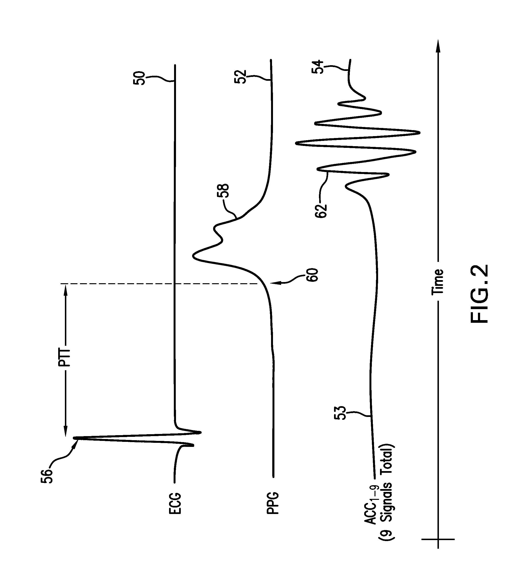
[0010]This invention provides a body-worn vital sign monitor featuring a series of sensors that measure time-dependent PPG, ECG, motion (ACC), and pressure waveforms to continuously monitor a patient's vital signs, degree of motion, posture and activity level. Blood pressure, a vital sign that is particularly useful for characterizing a patient's condition, is typically calculated from a PTT value determined from the PPG and ECG waveforms. Once determined, blood pressure and other vital signs can b

Problems solved by technology

This, in turn, can add u

Method used


Image

  • Method for measuring patient motion, activity level, and posture along with ptt-based blood pressure
  • Method for measuring patient motion, activity level, and posture along with ptt-based blood pressure
  • Method for measuring patient motion, activity level, and posture along with ptt-based blood pressure

Examples


Embodiment Construction

System Overview

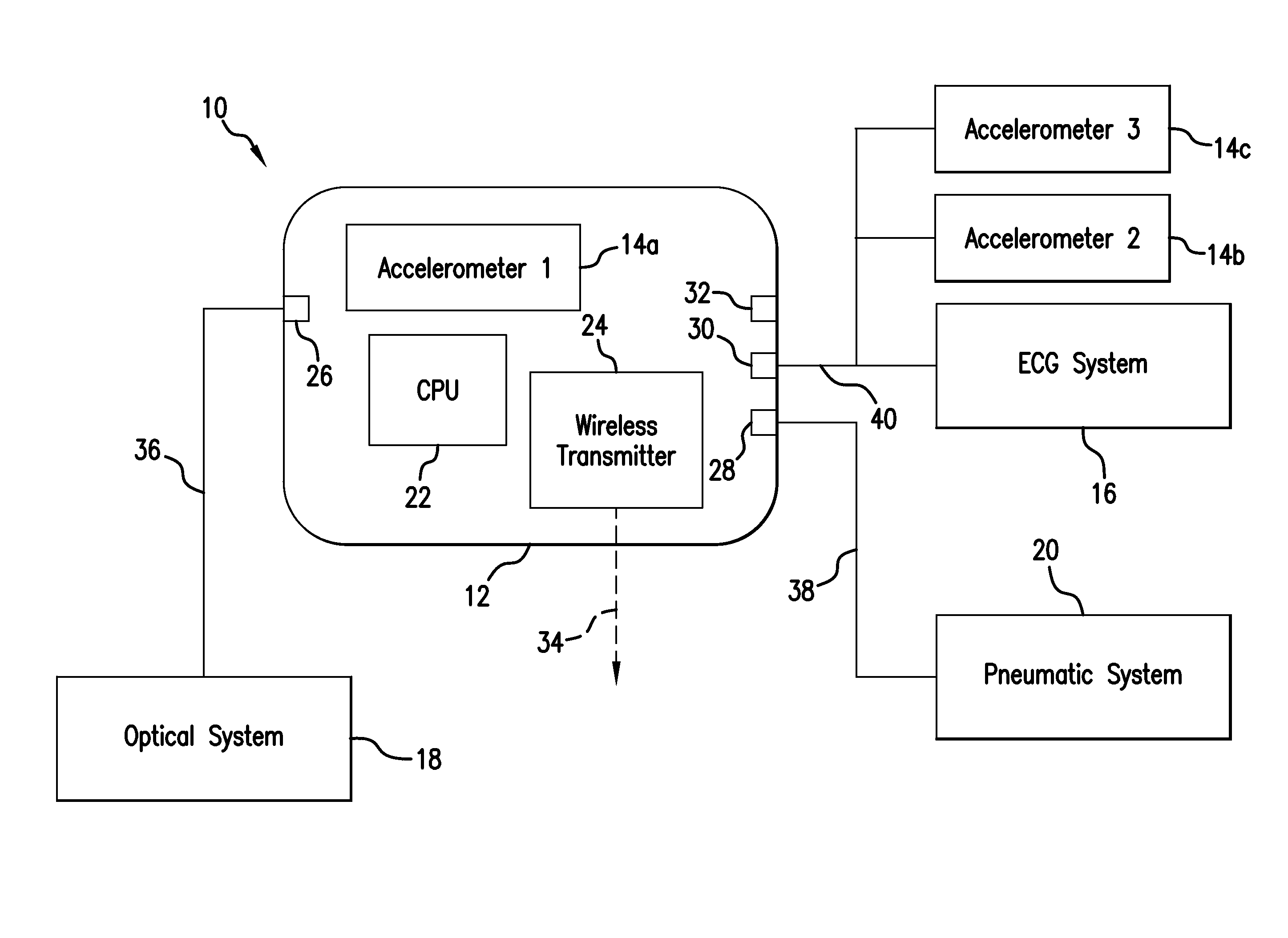
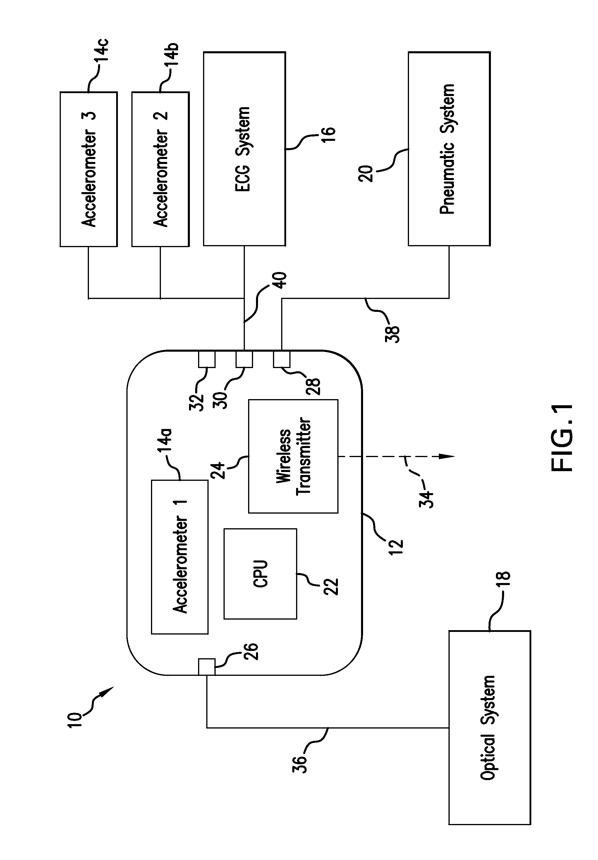
[0051]FIG. 1 shows a schematic drawing of a body-worn vital sign monitor 10 according to the invention featuring a wrist-worn transceiver 12 that continuously determines vital signs (e.g. SYS, DIA, SpO2, heart rate, respiratory rate, and temperature) and motion (e.g. posture, arm height, activity level, and degree of motion) for, e.g., an ambulatory patient in a hospital. The transceiver 12 connects to three separate accelerometers 14a, 14b, 14c distributed along a patient's arm and torso and connected to a single cable. Each of these sensors measures three unique ACC waveforms, each corresponding to a separate axis (x, y, or z), which are digitized internally and sent to a computer processing unit (CPU) 22 within the transceiver 12 for processing. The transceiver 12 also connects to an ECG system 16 that measures an ECG waveform, an optical system 18 that measures a PPG waveform, and a pneumatic system 20 for making cuff-based ‘indexing’ blood pressure measurements a...


PUM


Abstract

The invention provides a system and method for measuring vital signs (e.g. SYS, DIA, SpO2, heart rate, and respiratory rate) and motion (e.g. activity level, posture, degree of motion, and arm height) from a patient. The system features: (i) first and second sensors configured to independently generate time-dependent waveforms indicative of one or more contractile properties of the patient's heart; and (ii) at least three motion-detecting sensors positioned on the forearm, upper arm, and a body location other than the forearm or upper arm of the patient. Each motion-detecting sensor generates at least one time-dependent motion waveform indicative of motion of the location on the patient's body to which it is affixed. A processing component, typically worn on the patient's body and featuring a microprocessor, receives the time-dependent waveforms generated by the different sensors and processes them to determine: (i) a pulse transit time calculated using a time difference between features in two separate time-dependent waveforms, (ii) a blood pressure value calculated from the time difference, and (iii) a motion parameter calculated from at least one motion waveform.

Description

CROSS REFERENCES TO RELATED APPLICATION[0001]Not ApplicableSTATEMENT REGARDING FEDERALLY SPONSORED RESEARCH OR DEVELOPMENT[0002]Not ApplicableBACKGROUND OF THE INVENTION[0003]1. Field of the Invention[0004]The present invention relates to medical devices for monitoring vital signs, e.g., arterial blood pressure.[0005]2. Description of the Related Art[0006]Pulse transit time (PTT), defined as the transit time for a pressure pulse launched by a heartbeat in a patient's arterial system, has been shown in a number of studies to correlate to systolic (SYS), diastolic (DIA), and mean (MAP) blood pressure. In these studies, PTT is typically measured with a conventional vital signs monitor that includes separate modules to determine both an electrocardiogram (ECG) and pulse oximetry (SpO2). During a PTT measurement, multiple electrodes typically attach to a patient's chest to determine a time-dependent ECG component characterized by a sharp spike called the ‘QRS complex’. The QRS complex in...

Claims


Application Information

Patent Timeline
IPC IPC(8): A61B5/00A61B5/11A61B5/308
CPCA61B5/0002A61B5/6826A61B5/0205A61B5/021A61B5/02125A61B5/022A61B5/02225A61B5/02416A61B5/0285A61B5/0402A61B5/0452A61B5/1116A61B5/1117A61B5/1118A61B5/1123A61B5/447A61B5/681A61B5/6824A61B5/7207A61B5/7257A61B2560/0261A61B2562/0219A61B5/7239A61B5/02028A61B5/0082A61B5/14551A61B5/1122A61B5/746A61B5/044A61B5/0428A61B5/0408A61B5/0816A61B5/0024A61B5/6823A61B5/04085A61B5/04012A61B5/0295A61B5/0006A61B5/318A61B5/349A61B5/25A61B5/30A61B5/282A61B5/316A61B5/339
Inventor MCCOMBIE, DEVINDHILLON, MARSHALBANET, MATT
Owner SOTERA WIRELESS
Why Eureka
Try Eureka