
Electroporation device with improved tip and electrode support

Inactive Publication Date: 2010-11-25
SONION
View PDF18 Cites 25 Cited by
  • Summary
  • Abstract
  • Description
  • Claims
  • Application Information

AI Technical Summary

Benefits of technology

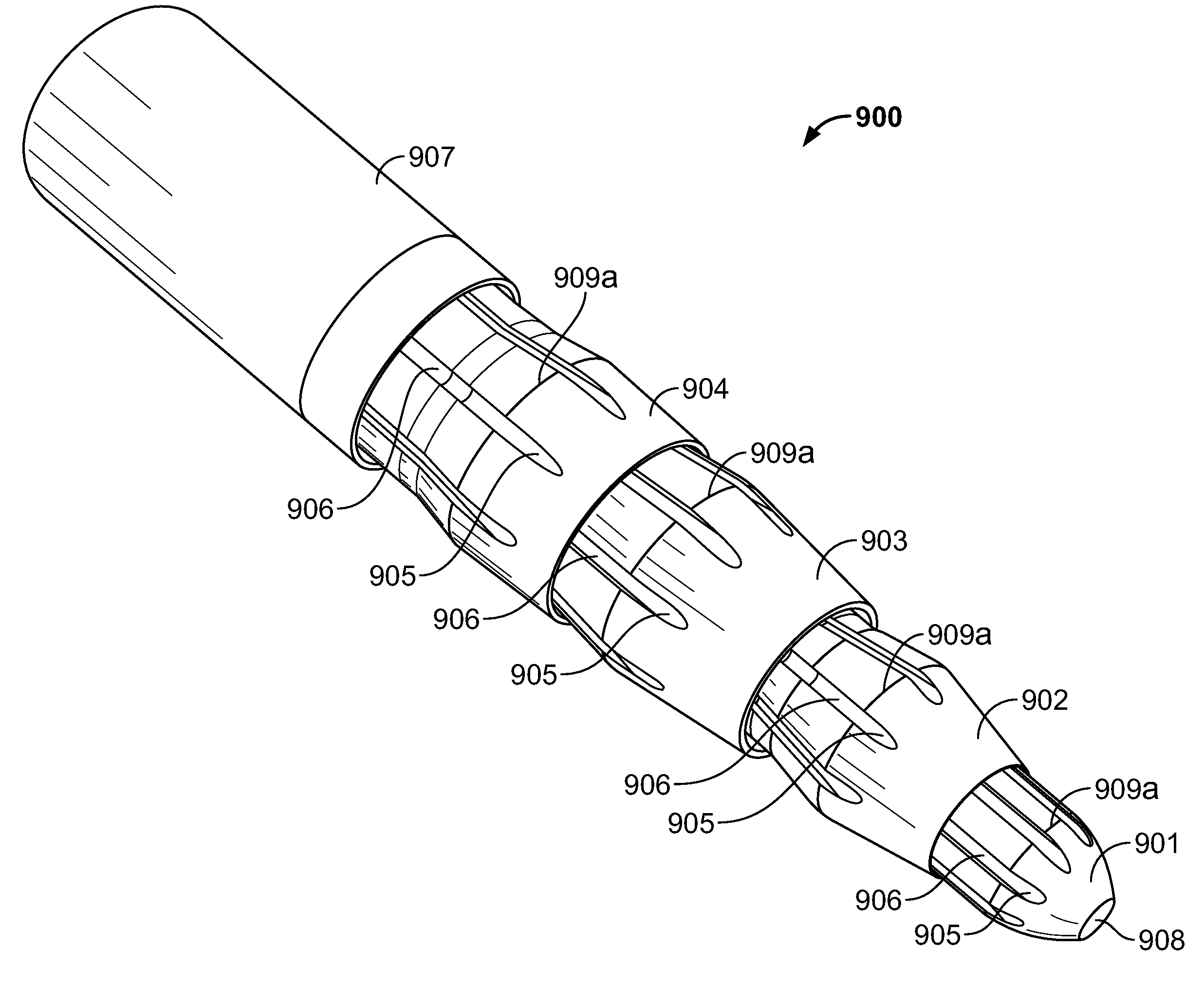
[0012]In accordance with the present invention, the rotationally symmetrical member of the distal tip simplifies miniature assembly and effective space utilization of an inner lumen of the elongate introducer shaft. These are important advantages because the outer dimensions of an electroporation device, in particular invasive portions thereof, are generally made a small as practically feasible to minimize tissue injury during advancement of the elongate introducer shaft through patient tissue. The set of electrode channels may be configured as a compact annularly shaped array of electrodes channels, or even several coaxially-arranged annularly shaped sets electrode channels, where spatial positions of individual electrode channels are aligned with corresponding spatial positions of the tip electrode channels so as to make alignment bushings or similar electrode redirection members superfluous.
[0044]Preferably, each electrode tube of the first set of electrode tubes is arranged outside or inside a single electrode tube of the second set of electrode tubes. This one-to-one telescopic arrangement of individual electrode tubes of the first and second sets allows a close proximity between concentric wall sections and close conformance of the inner electrode tube to an outer surface contour of the electrode to provide a compact arrangement.

Problems solved by technology

In the treatment of diseases in the brain, e.g. brain cancer, as well as diseases in other anatomical areas of a body, physical access to a diseased tissue region may be a challenge.
Furthermore, efficient delivery and subsequent uptake of therapeutic molecules, such as a drug or genetic compound, to an anatomical target tissue often presents a significant challenge.
In this process, burning / scarring of target and / or adjacent tissue is strongly undesirable, since it may interfere with the uptake of molecules through changes in tissue conductivity.
Another potential problem associated with the structure of the disclosed multi-element tip is the risk of tip element detachment of the wedge-shaped elements during insertion of the electroporation device.
However, the wedge-shaped contour and orientation of the individual wedge-shaped members or tip elements make these prone to sliding out or drifting apart along the central longitudinal axis of the introducer shaft without an adequate locking mechanism coupled to the tip elements.
Tip element detachment constitutes a potential patient safety hazard because the fork-shaped contour that will result if the wedge-shaped members slide apart.
This problem is particularly pronounced for electroporation devices with small dimensions which imply severe size constraints of the electrodes making these vulnerable to bucking or bending forces during electrode advancement.

Method used


Image

  • Electroporation device with improved tip and electrode support
  • Electroporation device with improved tip and electrode support
  • Electroporation device with improved tip and electrode support

Examples


Embodiment Construction

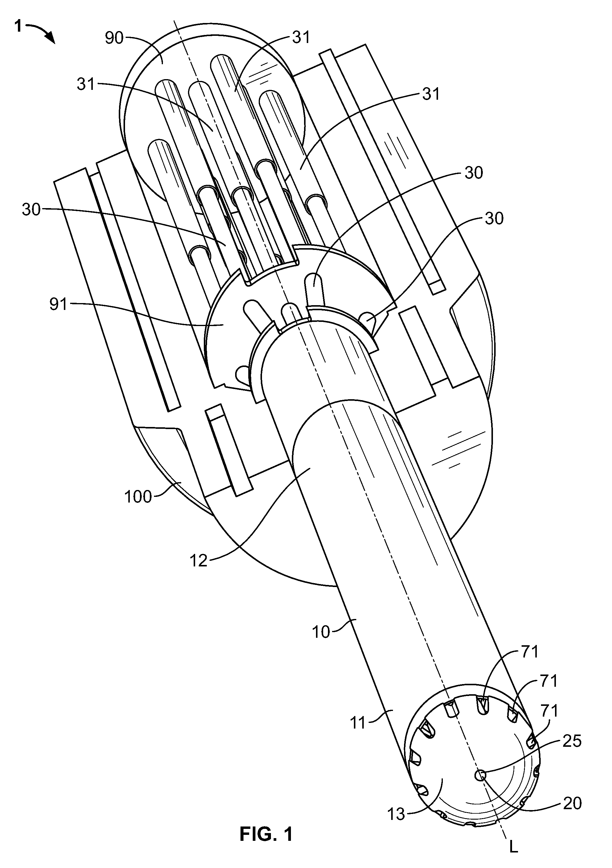
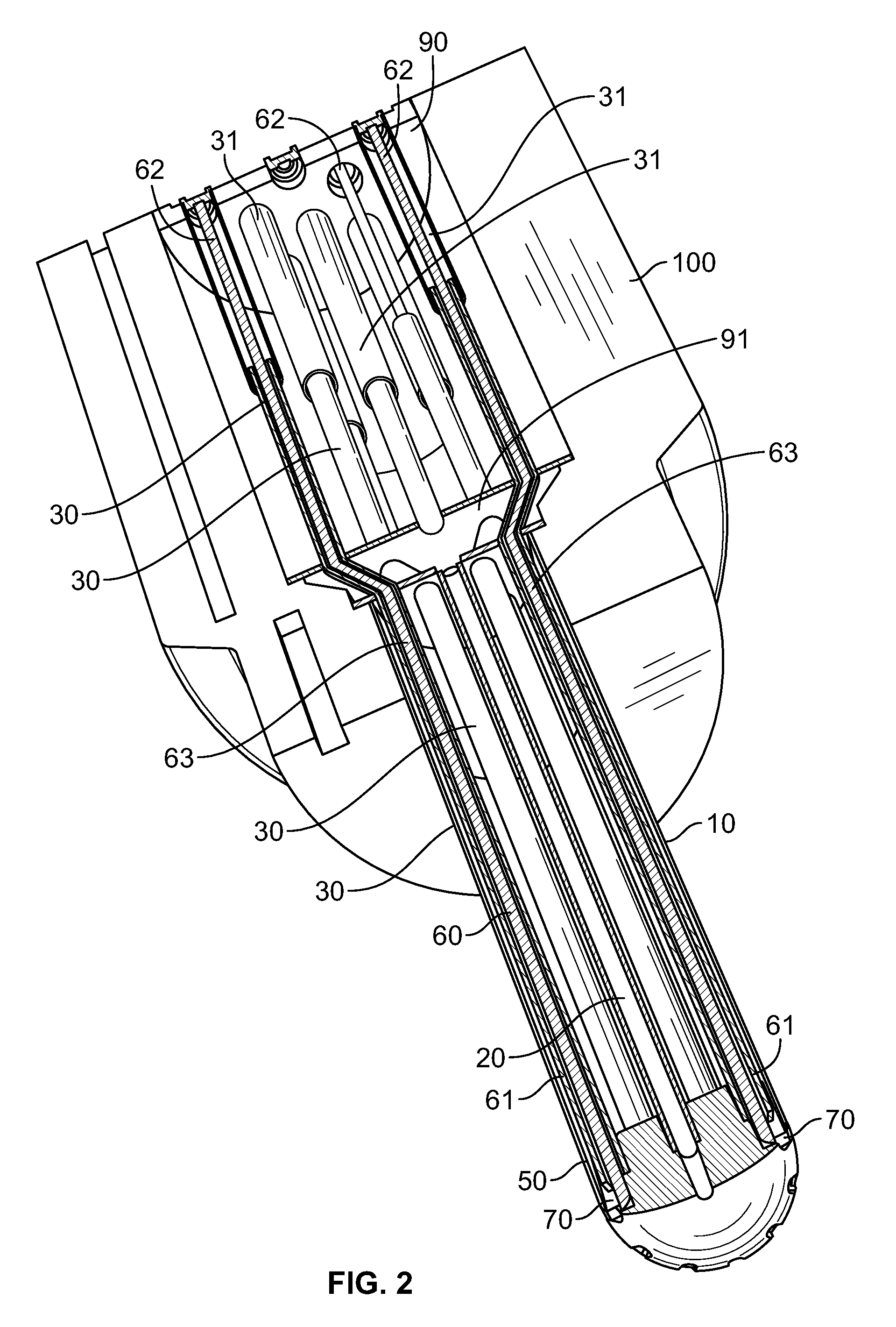
[0061]FIG. 1 illustrates an electroporation device 1 according to a preferred embodiment of the invention. The electroporation device 1 comprises a handle section 100 and an elongate and essentially tubular introducer shaft 10 or shaft preferably having a length suitable for accessing deeper-lying tissue regions. The length of the shaft 10 may be adapted for the intended use. The shaft 10 is attached to the handle section 100, and has a proximal end 12 adjacent to the handle section 100 and a distal end 11. The shaft 10 may in one embodiment be fixedly attached to the handle section. In other embodiments the shaft 10 may be detachably mounted to the handle section 100, and may comprise suitable connector mechanisms for establishing detachable electrical and mechanical interconnection, e.g. for conducting electrical pulses. A distal tip 13, that is preferably shaped to permit the creation of a channel through intervening layers of tissue while causing minimal damage to said tissue, i...


PUM


Abstract

An electroporation device having a handle section, a set of electrodes, and an electrode guide assembly. The handle section is operatively connected to an elongate introducer shaft, which has a longitudinal axis and a distal tip. The set of electrodes includes respective distal electrode tips. The electrode guide assembly is arranged inside the elongate introducer shaft and includes a set of electrode channels with each electrode channel guiding one or several electrodes. Each electrode is slidably arranged within an electrode channel between (a) a retracted position, where the distal electrode tips are enclosed inside the introducer shaft, and (b) an advanced position, where the distal electrode tips project to an outside of the introducer shaft. A set of longitudinally extending tip electrode channels are arranged in the distal tip and adapted to guide respective travel trajectories of the distal electrode tips during electrode advancement and retraction. The set of longitudinally extending tip electrode channels includes a set of electrode grooves disposed around a circumferential contour of a rotationally symmetrical member of the distal tip.

Description

CROSS-REFERENCE TO RELATED APPLICATION[0001]This application claims the benefit of U.S. Provisional Application Ser. No. 61 / 179,960, filed May 20, 2009, entitled “Electroporation device with Improved Tip and Electrode Support.”COPYRIGHT[0002]A portion of the disclosure of this patent document contains material which is subject to copyright protection. The copyright owner has no objection to the facsimile reproduction by anyone of the patent disclosure, as it appears in the Patent and Trademark Office patent files or records, but otherwise reserves all copyright rights whatsoever.FIELD OF THE INVENTION[0003]The present invention relates to an electroporation device with a distal tip which comprises a rotationally symmetrical member. A set of longitudinally extending tip electrode channels comprises a set of electrode grooves disposed around a circumferential contour of the rotationally symmetrical member. According to another aspect of the present invention there is provided an elect...

Claims


Application Information

Patent Timeline
IPC IPC(8): A61N1/30
CPCA61N1/327
Inventor STAAL, LASSE GULDBORGDRAGE, RUNE HENRI WINCENTYLARSEN, RENE
Owner SONION
Features
  • Generate Ideas
  • Intellectual Property
  • Life Sciences
  • Materials
  • Tech Scout
  • Unparalleled Data Quality
  • Higher Quality Content
  • 60% Fewer Hallucinations
Learn More