Unlock instant, AI-driven research and patent intelligence for your innovation.

Systems and Methods for Low-Latency Encrypted Storage

Active Publication Date: 2010-11-25
SYNAPTICS INC
View PDF15 Cites 72 Cited by
  • Summary
  • Abstract
  • Description
  • Claims
  • Application Information

AI Technical Summary

Benefits of technology

[0022]An encrypted storage can employ CTR mode encryption to reduce latency during data retrieval from storage. The storage comprises a memory, an encryption module and an XOR module. To retrieve data stored in the encrypted storage from a particular memory address, a counter function converts the memory address into an address based counter. The address based counter is then encrypted into an address based pad. The XOR module receives input data retrieved from the encrypted storage and produces plaintext data by XORing the address based pad with the input data. In the simplest implementation, the input data is the ciphertext data retrieved from the encrypted storage. Optionally, light encryption may be applied in the encryption process. In such a circumstance, “light decryption” can be applied to the ciphertext data retrieved from the encrypted storage to produced input data supplied to the XOR module. In addition random padding added during the encryption process can also be discarded prior to reception by the XOR module.

Problems solved by technology

However, one-time pad ciphers are impractical.
Generally, streaming modes such as CBC, PCBC, CFB and OFB are useful for communications where information is sent in streams, they are not very efficient for storage applications.
However, if storage 606 is memory such as static random access memory (SRAM) or dynamic random access memory (DRAM), where memory is access in a random access fashion, streaming modes are not practical.
ECB could be used, but the encryption / decryption operations can introduce unacceptable latency in accessing memory.
If ECB is used, the block cipher operation of ECB must begin after the ciphertext data is retrieved and would not allow for parallel operations and hence would add decryption time to the latency of data retrieval.

Method used


Image

  • Systems and Methods for Low-Latency Encrypted Storage
  • Systems and Methods for Low-Latency Encrypted Storage
  • Systems and Methods for Low-Latency Encrypted Storage

Examples


Embodiment Construction

[0064]A detailed description of embodiments of the present invention is presented below. While the disclosure will be described in connection with these drawings, there is no intent to limit it to the embodiment or embodiments disclosed herein. On the contrary, the intent is to cover all alternatives, modifications and equivalents included within the spirit and scope of the disclosure as defined by the appended claims.

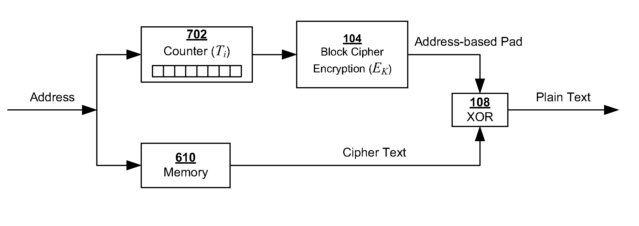
[0065]As described above, in certain applications, it is desirable to encrypt fast storage devices such as dynamic random access memory (DRAM) and static random access memory (SRAM). Chaining and feedback modes are not suitable for random access to data such as in random access memory (RAM). ECB can work, but introduces latency due to the need to encrypt and decrypt every block.

[0066]Although CTR mode is often used as a stream cipher, where the counter block is of the construction described in FIG. 5C, it need not be a stream cipher if a different construction is used ...


PUM


Abstract

Encrypted storage often introduces unwanted latency in access. This delay can result in a processor having to wait for critical data thus slowing performance. Generally speaking, the latency is at most an issue when reading from encrypted storage, since the processor may need the information read from encrypted storage to proceed. During a write operation, there typically is not an issue because the processor does not need to wait for the end of the write operation to proceed. A variant of counter (CTR) mode for a block cipher can be used to perform the majority of the decryption operation without knowledge of the ciphertext, therefore the majority of the decryption operation can be performed concurrently with the retrieval of the ciphertext from memory. In order to further secure the encrypted storage, a light encryption can be performed to further obfuscate the ciphertext.

Description

BACKGROUND OF THE INVENTION[0001]1. Field of the Inventions[0002]The invention relates generally to encryption for storage and specifically to the use of block ciphers in modified counter mode for encrypted storage.[0003]2. Background Information[0004]A symmetric cipher is an encryption system which uses the same key for encrypting and decrypting messages. Therefore, the encrypting party and the decrypting party have to share this key. A message that is to be encrypted is known as a plaintext message and once the message is encrypted it is referred to as a ciphertext message. In particular, a block cipher encrypts a fix size plaintext message into a fixed size ciphertext message. Typically the size of the plaintext and ciphertext are the same referred to as the block size. In the operation of a block cipher, the same plaintext yields the same ciphertext when encrypted with the same key.[0005]FIG. 1 illustrates a typical block cipher. Plaintext (P) 102 is fed into block cipher 104 an...

Claims


Application Information

Patent Timeline
IPC IPC(8): G06F12/14
CPCG06F12/1408G06F21/78G06F21/85H04L9/0637H04L2209/20H04L2209/08H04L2209/125G06F2221/2107
Inventor MILLER, MARK E.
Owner SYNAPTICS INC