
Container with air guide

Active Publication Date: 2010-12-02
MAERSK CONTAINER IND
View PDF19 Cites 3 Cited by
  • Summary
  • Abstract
  • Description
  • Claims
  • Application Information

AI Technical Summary

Benefits of technology

[0005]The purpose of the invention is to overcome the disadvantages of the known air guides mentioned above. This is achieved in that the container is provided with a spring arrangement that counteracts a movement of the air guide in the direction of the end wall. This causes that both stop chocks and stop brackets can be avoided, as the spring arrangement will automatically reset the air guide to its operation position, when it has been pushed in, so that also the cross-section and the function of the channel are restored. When the stop chocks and stop brackets are left out, the air guide can be pushed onto the end wall without meeting any obstructions, which reduces the risk of damaging the air guide.
[0007]Preferably, the spring arrangement is formed by a part of the air guide itself, for example in that the air guide is made of a resilient material. This will on the one side save manufacturing costs and on the other side the cleaning of the spring arrangement will be facilitated. Further, this substantially increases the resistance of the air guide towards the forces acting upon it.

Problems solved by technology

Further, this substantially increases the resistance of the air guide towards the forces acting upon it.

Method used


Image

  • Container with air guide
  • Container with air guide
  • Container with air guide

Examples


Embodiment Construction

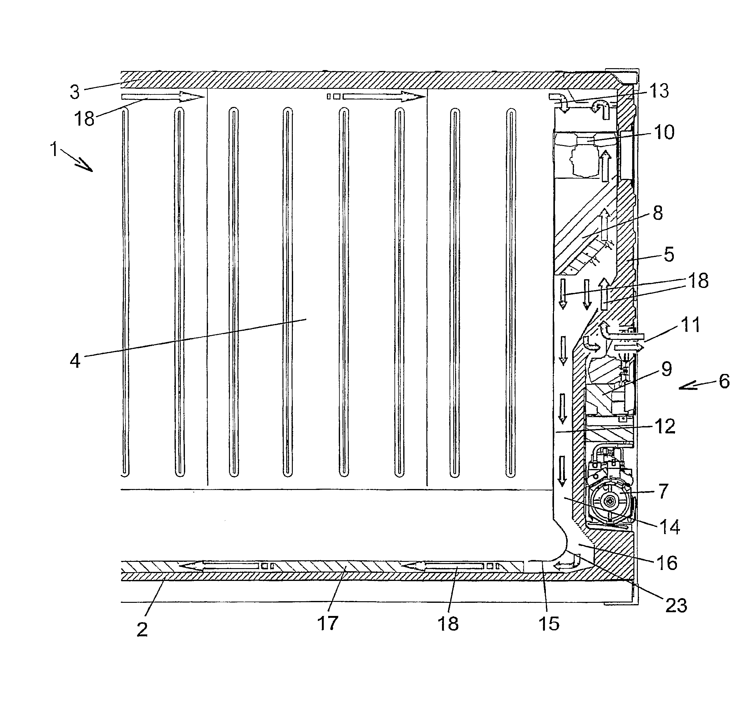
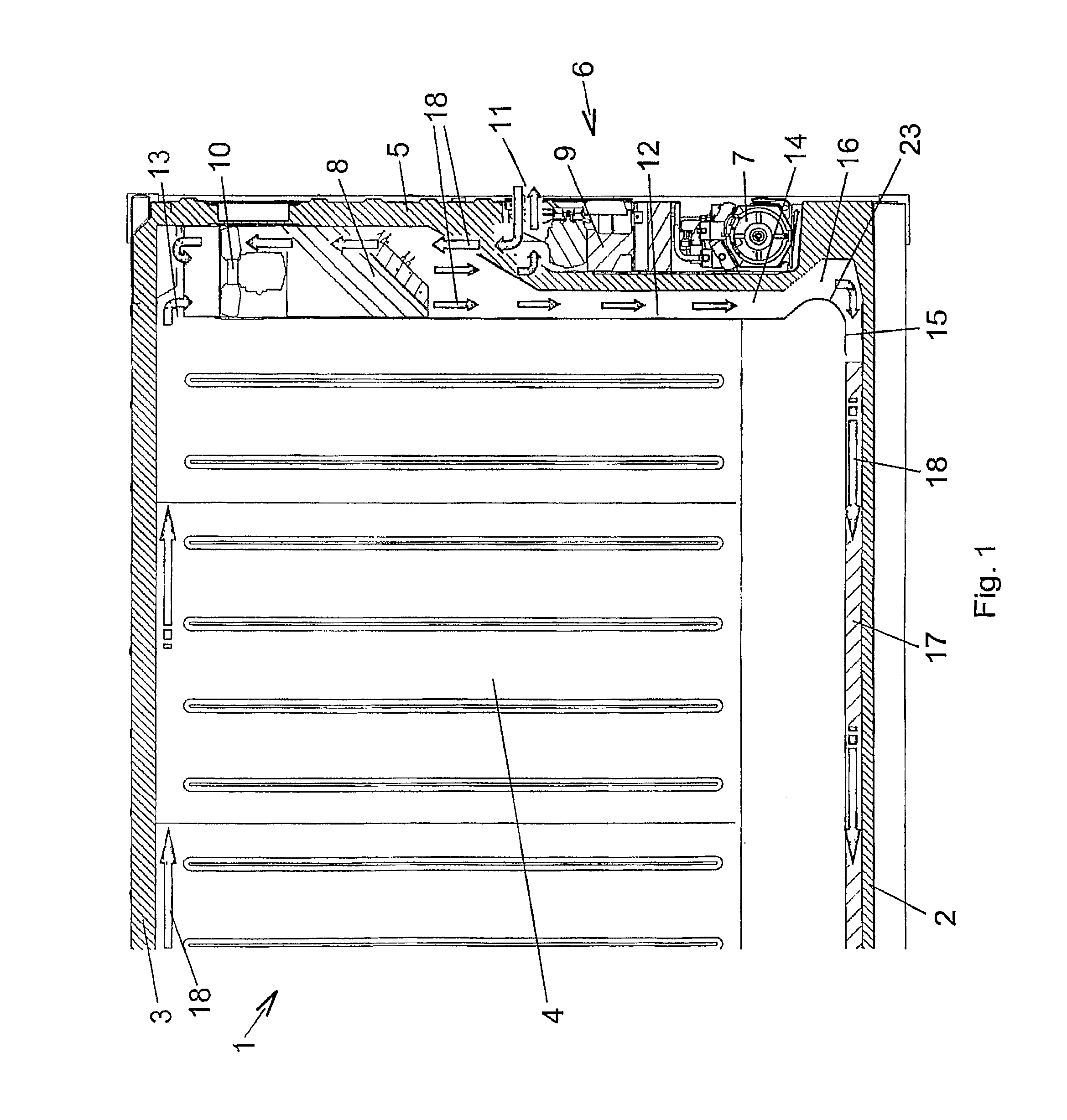
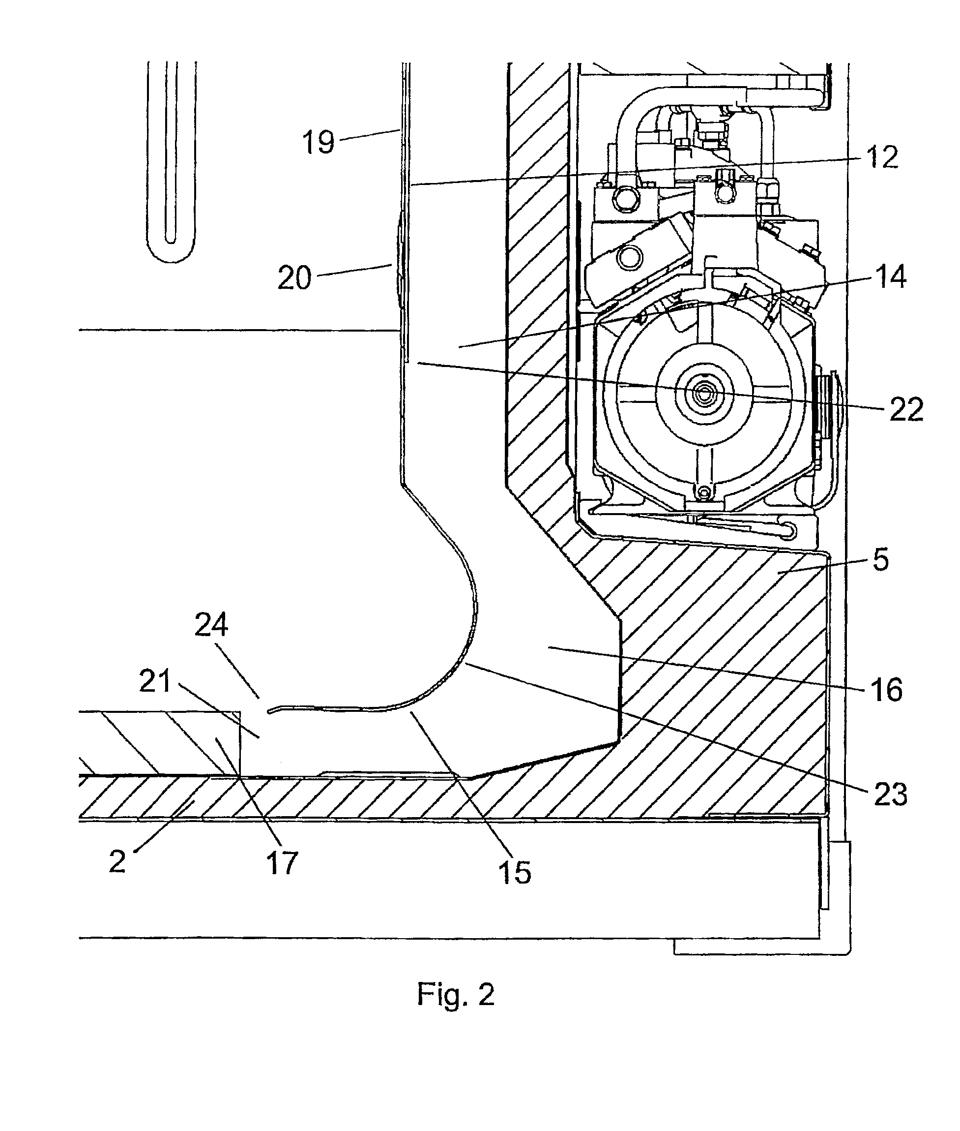
[0024]The container in FIG. 1 comprises a floor 2, a roof 3, two side walls 4 and an end wall 5. Further, the container has a second end wall, which is not shown, thus forming a closed inner chamber. In order to achieve a food thermal isolation of the inner chamber of the container 1 in relation to the environment, isolating layers are integrated in the floor 2, the roof 3 and the walls 4, 5. A cooling system 6 known in the art and comprising several components, for example a compressor 7, an evaporator 8, a compressor 9, a fan 10 and a two-way valve 11, is integrated in the end wall 5. Towards the inside of the container 1, the cooling system 6 has a dividing wall 12 that defines an upper opening 13 and a lower opening 14. The upper opening 13 serves the suction of the return air from the container 1, and the lower opening 14 serves the supply of the cooled air into the container 1. Between the lower opening 14 and the floor 2 an air guide 15 is arranged to form an air channel 16 t...


PUM


Abstract

In a container 1 with an end wall 5, an air treatment system 6 that is arranged in the end wall 5 and comprises an opening 14 on its bottom side, through which it emits an air flow, a floor 2 provided with channels guiding the air flow in a direction away from the end wall 5, and an air guide 15 forming, in an operation position, together with a part of the end wall 5 and a part of the floor 2 an air channel 16 that guides the air flow between the opening 14 and the channels in the floor, it is endeavoured to prevent the air guide from being damaged by the forks of a fork lift truck. This is achieved in that the container 1 comprises a spring arrangement that counteracts a movement of the air guide 15 in the direction of the end wall 5.

Description

CROSS REFERENCE TO RELATED APPLICATIONS[0001]This application is entitled to the benefit of and incorporates by reference essential subject matter disclosed in International Patent Application No. PCT / DK2008 / 000426 filed on Dec. 2, 2008 and Danish Patent Application No. PA 2007 01730 filed Dec. 4, 2007.FIELD OF THE INVENTION[0002]The present invention relates to containers and, more particularly, to air guides therefor.BACKGROUND OF THE INVENTION[0003]When transporting sensitive goods, like fruit, vegetables and plants, certain environmental conditions must be observed. Therefore, containers for the transport of such goods are typically provided with air treatment systems, like cooling, heating, dehumidification and / or humidification systems. In standardised containers, which are, for example, used for overseas transports, the system is usually arranged in an end wall, where the treated air is delivered downwards and the return air from the inside of the container is sucked in from ...

Claims


Application Information

Patent Timeline
IPC IPC(8): F25D31/00F25D17/04
CPCB65D88/745F25D17/06F25D11/003
Inventor JOERGENSEN, GERTLUBKER, LARS
Owner MAERSK CONTAINER IND
Learn More