Point Of Use Actuator

a point-of-use actuator and actuator technology, applied in the direction of servomotor components, machines/engines, servomotor circuits, etc., can solve problems such as leaking hydraulic fluids, potential challenges, safety and environmental problems, etc., and achieve the effect of efficient space saving advantages

Inactive Publication Date: 2010-12-02
HALDEX HYDRAULICS
View PDF14 Cites 17 Cited by
  • Summary
  • Abstract
  • Description
  • Claims
  • Application Information

AI Technical Summary

Benefits of technology

[0027]Accordingly, it is an object of the present invention to provide a hydraulic system that eliminates the need for external hoses that are susceptible to damage and leaks. It is a further object of the invention to provide a hydraulic system that efficiently contains space saving advantages from the integration of components. It is an object of the invention to provide a hydraulic system that integrates the components of a hydraulic system and actuator. It is yet a further object of this invention to provide a hydraulic system with a non-vented reservoir. It is still another object of the invention to provide a hydraulic system with an air tight sealed reservoir with expandable bladder. It is a yet another object of this invention to orient hydraulic system without worrying about cavitation.

Problems solved by technology

In the process of assembly of hydraulic systems, the potential for challenges may be presented due to tight space constraints, degradation, and damage from mechanical or human movements.
Hydraulic systems suffer from assemblies that consume too much space, or have their plumbing damaged, which can result in leaking hydraulic fluids.
Plumbing damage may cause various safety and environmental issues.
Plumbing damage can also reduce system performance from flow restrictions, and can cause pressure differentials throughout the hydraulic system.
This may result in a less efficient hydraulic system.
Device examples often orient the linear actuator in a position that prevents gravity to be considered for retraction, have retraction speed requirements that exceed gravity dependency, or may not have an adequate load weight to assist gravity dependency.
When the pump, reservoir, valves and hydraulic cylinders are connected together, the end result may be a large number of hoses, fittings, pipes and valves located in damage-prone areas.
External hoses consume space and are susceptible to damage when in areas where mechanical or human movements occur.
These components may be difficult and / or expensive to replace.
Not only are the hoses susceptible to being punctured, but they may be damaged through environmental degradation.
Furthermore, these prior art systems that include hoses and / or pipes may have leakage problems, which can cause environmental, safety, and maintenance issues.
Connecting elements can also leak.
External pipes and / or hoses may tend to increase flow restrictions that cause pressure differentials and reduce system efficiency.
Furthermore, problems with flow restrictions in a hydraulic system are exacerbated as the fluid becomes more viscous, e.g. as temperature falls.
Aerated fluid attributes to cavitation effects within a pump with resulting component damage and generated contaminates.
Water attributes to additional oxidation of certain reservoir and system component materials with resulting generated contaminants.
Contaminates can present several performance related issues for a hydraulic system comprising of components that move within tight clearances and incorporate small passages.
Furthermore, prior art designs of hydraulic systems contain limitations whereby orientation of hydraulic power units with vented reservoirs must ensure that the pump inlet remains submerged below the oil level in order to prevent cavitation.
If a power unit with an exposed vented reservoir is mounted directly to an actuator, it can create additional space demands to ensure proper clearances, reservoir venting, and pump inlet position, as the actuator may require axial movements.
What is desired therefore is to provide a hydraulic system that reduces the need for external hoses that may be susceptible to damage and leaks, resulting in safety issues.

Method used


Image

  • Point Of Use Actuator
  • Point Of Use Actuator
  • Point Of Use Actuator

Examples


Embodiment Construction

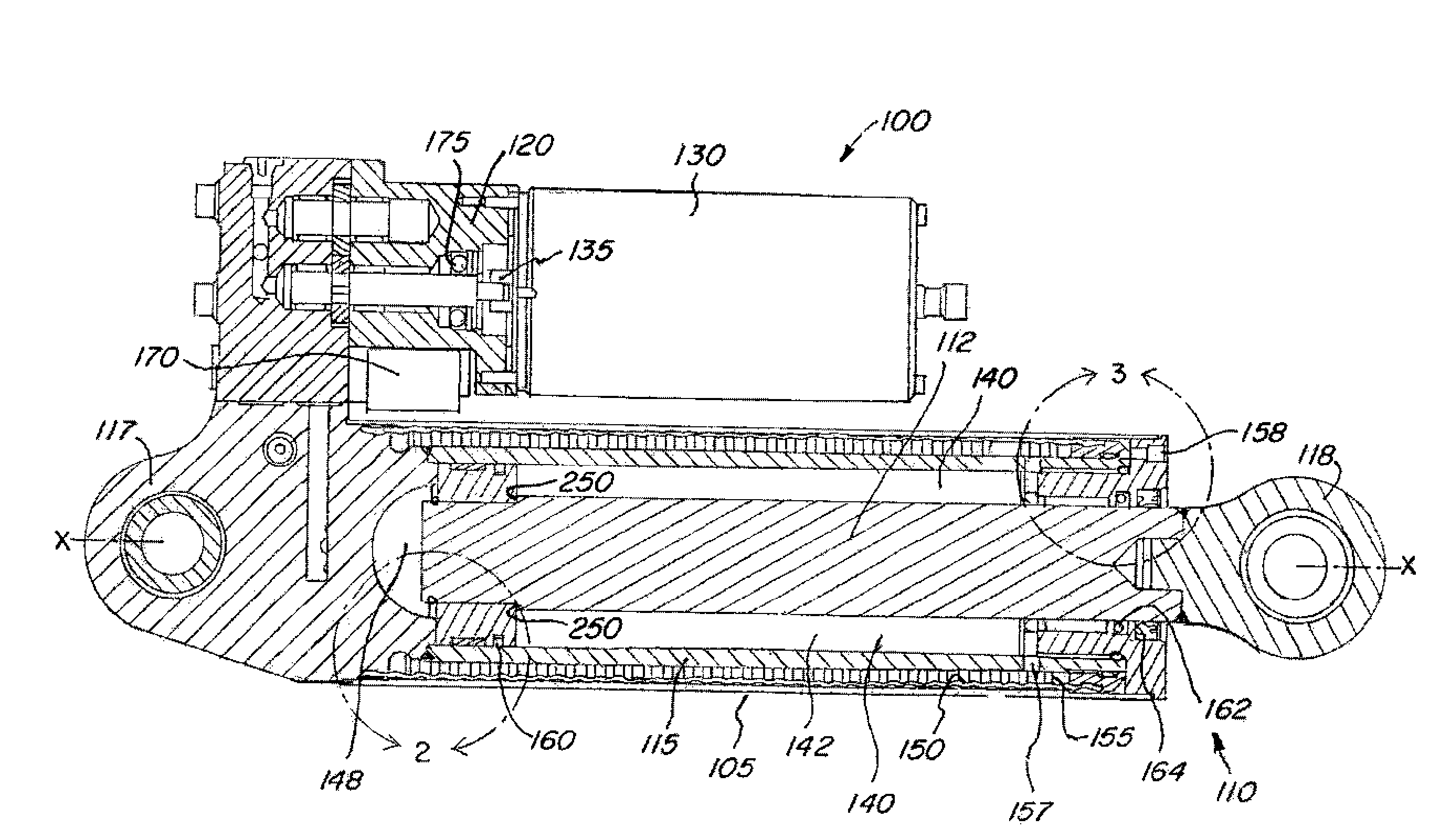
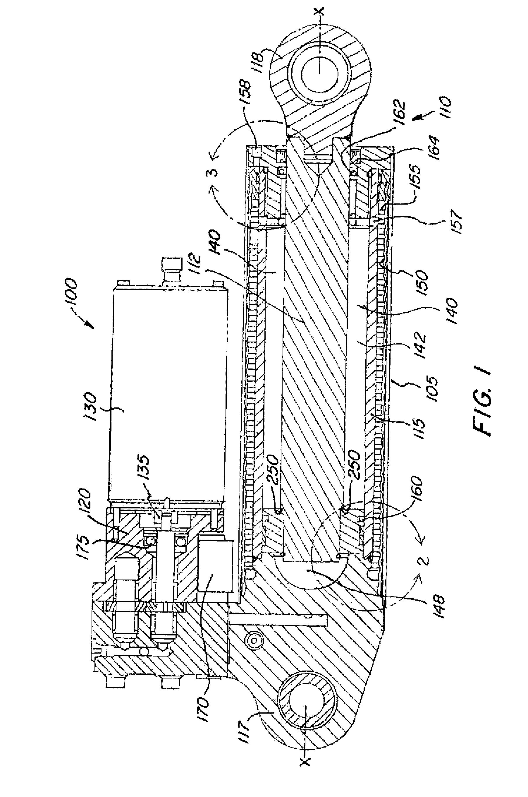
[0060]Referring to FIG. 1, a hydraulic system 100 in accordance with the present invention is shown. Hydraulic system 100 eliminates the need for external hoses that are susceptible to damage and leaks. System 100 efficiently contains space saving advantages from the integration of components.

[0061]The hydraulic system comprises an actuator 110 capable of moving under drive from hydraulic fluid 1000 (not shown), a pump 120 mounted to the actuator 110 for moving fluid 1000, a motor 130 driving the pump 120, and a non-vented reservoir 140 that provides fluid 1000 to extend the actuator 110. The actuator 110 contains an actuator rod 112, actuator tube 115, and two mounting provisions 117 and 118. When the actuator is actuated, the actuator rod 112 moves in an axial direction parallel to the longitudinal axis X of the actuator 110.

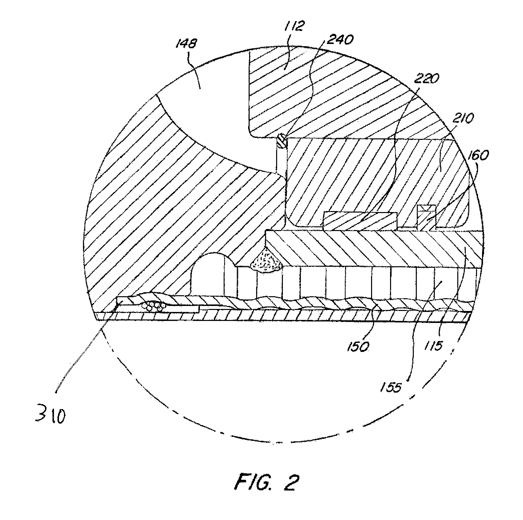
[0062]The rod side volume of the reservoir 140 is shown as 142. The bladder volume 155 is also next to volume of reservoir 140. Thus, some of the volume of th...


PUM


Abstract

A hydraulic actuator system designed to inwardly contain major portions of its control system. The system includes a unique non-vented and air tight sealed reservoir with expandable bladder. This inward control system and non-vented reservoir optimize space saving advantages and eliminate the need for external elements typically used in a hydraulic system, while extending fluid life, reducing cavitation and fluid oxidation, and increasing performance in the hydraulic system. The system configurations can work for both a single or dual acting linear actuator and further can involve a motor, hydraulic pump, and electro-hydraulic valve circuit used to control fluid throughout the system.

Description

FIELD OF THE INVENTION[0001]The present invention relates to an improved hydraulic system for single and dual acting linear actuators if appropriately configured. More particularly, the invention is a hydraulic system designed to inwardly contain major portions of its control system. The invention further includes a unique non-vented and air tight sealed reservoir with expandable / retractable bladder. This inward control system and non-vented reservoir optimize, such as plumbing, space saving advantages and eliminates the need for external elements typically used in a hydraulic system, while extending fluid life by preventing cavitation and fluid oxidation in the hydraulic system.BACKGROUND OF THE INVENTION[0002]Hydraulic systems are generally made up of various components and assemblies that are externally plumbed together. In the process of assembly of hydraulic systems, the potential for challenges may be presented due to tight space constraints, degradation, and damage from mecha...

Claims


Application Information

Patent Timeline
Patent Type & Authority Applications(United States)
IPC IPC(8): F15B13/02F15B1/26
CPCF15B15/18F15B2211/27F15B2211/50527F15B2211/3057F15B2211/3051
Inventor KADLICKO, GEORGESTONE, WADE
Owner HALDEX HYDRAULICS
Why Eureka
Try Eureka