Temperature control system for seat of vehicles

a temperature control system and vehicle technology, applied in the field of temperature control systems, can solve the problems of increasing electric power consumption, deteriorating cooling and heating performance, and difficulty in optimizing heating and cooling efficiency and integrating the system, so as to improve heat exchange efficiency, simplify the overall structure of the temperature control system, and optimize heat exchange efficiency

Inactive Publication Date: 2010-12-02
CHUNG SANG HO
View PDF15 Cites 31 Cited by
  • Summary
  • Abstract
  • Description
  • Claims
  • Application Information

AI Technical Summary

Benefits of technology

[0019]According to the present invention, since the air duct forms a single air passage so that air flowing therein sequentially undergoes heat exchanges with the seat back temperature control unit and the seat cushion temperature control unit, the overall structure of the temperature control system is simplified and air having undergone heat exchange is discharged through a single passage so that a mechanism for preventing air after the heat exchange from being discharged directly toward a passenger does not need.
[0020]Further, since the seat back temperature control unit and the seat cushion temperature control unit are respectively provided with separate fans for supplying temperature-controlled air, the temperature control function for the seat back and the seat cushion can be optimized.
[0021]Further, since the heat transfer areas of the heat exchangers which are disposed in the air duct are respectively greater than the heat transfer areas of the heat exchangers which are disposed in the air passages for supplying air to the seat back and the seat cushion, the heat exchange efficiency can be enhanced when cooled air is supplied to the seat back and the seat cushion. In particular, since the heat transfer areas of the heat exchangers which are disposed in the air duct are 2.5 to 3 times greater than the heat transfer areas of the heat exchangers which are disposed in the air passages for supplying air to the seat back and the seat cushion, the heat exchange efficiency can be optimized when cooled air is supplied to the seat back and the seat cushion.
[0022]Still further, since the condensed water passages for sending condensed water generated on the surface of the heat exchanger which is disposed in the air passage for supplying air to the seat back and the seat cushion to the heat exchanger which is disposed in the air duct are provided, condensed water which is generated after the cooling operation can be effectively evaporated by the heated heat exchanger which is disposed in the air duct. Accordingly, it can be prevented that the accumulated condensed water causes stench or bacteria grows in the accumulated condensed water.
[0023]Still further, since the air duct is formed to suck air behind the seat back and to discharge air below the seat cushion, air having undergone heat exchange can be prevented from being discharged directly toward a passenger even without an additional structure.

Problems solved by technology

In the conventional temperature control system, the heat absorption part and the heat radiation part of the thermoelectric module are disposed within an air duct, so it is difficult and limited to optimize the heating and cooling efficiency and to integrate the system.
Further, since in the conventional temperature control system of a vehicle seat sucked air (operating medium) is sent to heat exchangers after being diverged into the heat absorption part and the heat radiation part and heat transfer areas of the heat exchangers of the heat absorption part and the heat radiation part are equal to one another, the cooling and heating performances are deteriorated.
In order to overcome the problem of deterioration of the cooling and heating performances, capacities of the blower and the thermoelectric module should be increased, and this increases electric power consumption and thereby electric efficiency is deteriorated.
Further, since in the conventional temperature control system of a vehicle seat air is indirectly distributed by a blower which is installed at a center of an air duct passing by a seat cushion and a seat back, length of the air passage for supplying air to the seat cushion and the seat back becomes longer so that cooling and heating efficiencies are deteriorated.
Still further, since in the conventional temperature control system of a vehicle seat a heat absorption part and a heat radiation part are separated within an air duct, condensed water which is generated around a heat exchanger after cooling operation is stopped may be accumulated within the air duct, and the accumulated condensed water may cause stench.

Method used


Image

  • Temperature control system for seat of vehicles
  • Temperature control system for seat of vehicles
  • Temperature control system for seat of vehicles

Examples


Embodiment Construction

[0031]Hereinafter, embodiments of the present invention will be explained with reference to the drawings.

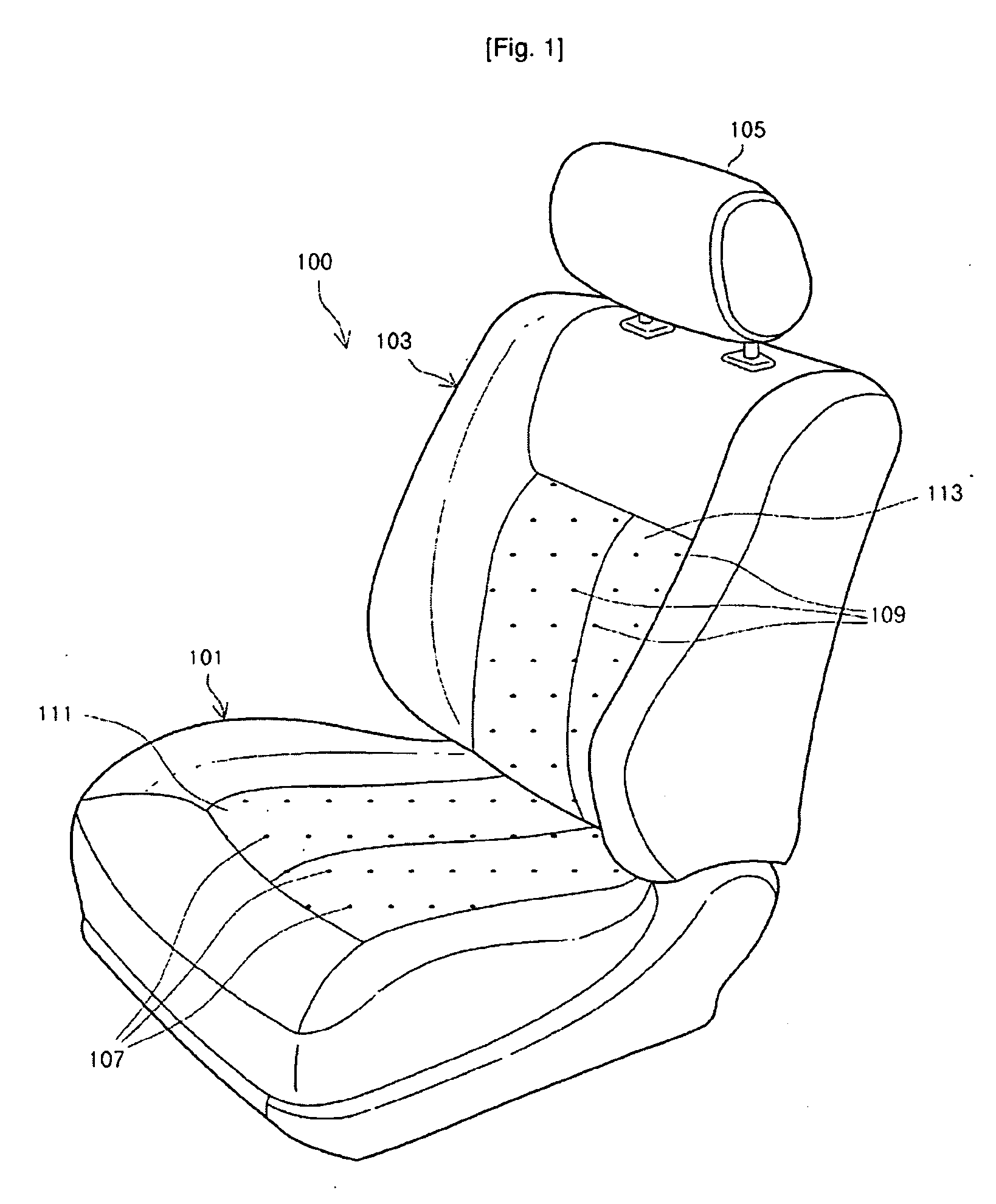
[0032]FIG. 1 is a perspective view of a vehicle seat 100 to which a temperature control system according to an embodiment of the present invention is adopted.

[0033]Referring to FIG. 1, the vehicle seat 100 includes a seat cushion 101 and a seat back 103. The seat cushion 103 is connected to the seat cushion 101 in a substantially vertical direction, and a headrest 105 may be connected to an upper end of the seat back 103.

[0034]The seat cushion 101 and the seat back 103 respectively include covers 111 and 113 to which air holes 107 and 109 are respectively formed. Air temperature of which is controlled by the temperature control system according to an embodiment of the present invention is emitted through the air holes 107 and 109 so that temperature of the seat 100 is controlled.

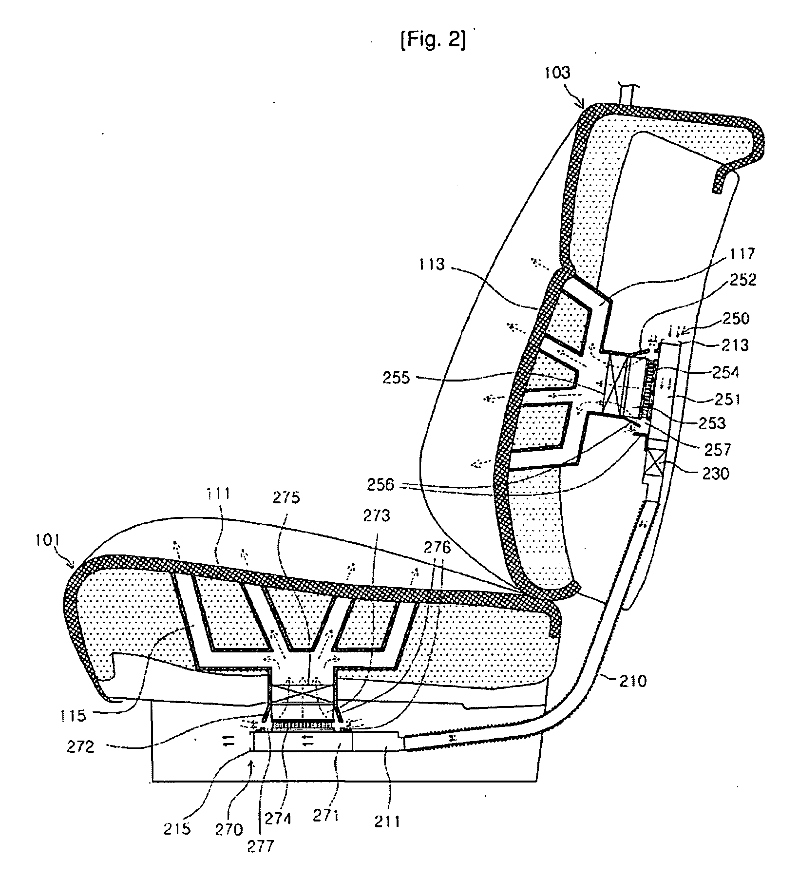
[0035]FIG. 2 is a cross-sectional view of a vehicle seat to which a temperature control system accordi...


PUM


Abstract

A temperature control system includes an air duct, an air-blowing device, a seat back temperature control unit, and a seat cushion temperature control unit. The air-blowing device urges air to flow through the air duct. The seat back temperature control unit and the seat cushion temperature control unit performs heat exchanges between air flowing in the air duct and air supplied to a seat back and air supplied to a seat cushion, respectively. The air duct forms a single air passage passing by the seat back temperature control unit and the seat cushion temperature control unit so that the air flowing in the air duct undergoes heat exchange with one of the seat back temperature control unit and the seat cushion temperature control unit and then undergoes heat exchange with the other.

Description

TECHNICAL FIELD[0001]The present invention relates to a temperature control system for controlling temperature of a seat of a vehicle, and more particularly, to a temperature control system for controlling temperature of a seat of a vehicle by allowing temperature-controlled heat (i.e., cooling or heating') medium to flow in a seat of a vehicle.BACKGROUND ART[0002]A temperature control system for heating or cooling a vehicle seat by flowing temperature-controlled operating medium in the vehicle seat has been introduced. The conventional temperature control system of a vehicle seat cools or heats the operating medium using a thermoelectric module (heat pump) and urges the heated or cooled operating medium to flow in the vehicle seat so as to control temperature of the vehicle seat.[0003]In the conventional temperature control system, the heat absorption part and the heat radiation part of the thermoelectric module are disposed within an air duct, so it is difficult and limited to opt...

Claims


Application Information

Patent Timeline
Patent Type & Authority Applications(United States)
IPC IPC(8): B60N2/56B60N2/90
CPCB60N2/5635B60N2/5678B60N2/5657A47C7/74B60N2/56
Inventor CHUNG, SANG-HO
Owner CHUNG SANG HO
Why Eureka
Try Eureka