Cold cathode ionization vacuum gauge, auxiliary discharge starting electrode, and vacuum processing apparatus

a vacuum processing apparatus and cold cathode ionization technology, applied in the direction of vacuum gauges using ionisation effects, instruments, measurement devices, etc., can solve the problems of delay affecting time, complex apparatus, time delay, etc., and achieve the effect of short period of time and performed stably

Active Publication Date: 2010-12-02
CANON ANELVA CORP
View PDF4 Cites 11 Cited by
  • Summary
  • Abstract
  • Description
  • Claims
  • Application Information

AI Technical Summary

Benefits of technology

[0015]The present invention makes it possible, without leading to complexity of the apparatus, to initiate discharge in a short period of time even when a sputtered film and / or a product is / are adhered to the inside of a gauge head of a vacuum gauge due to long term use. In addition, discharge can be performed stably after started.

Problems solved by technology

There is, however, a time delay between when a high voltage is applied to the cold cathode ionization vacuum gauge and when a discharge current begins to flow upon start of sustained discharge.
This time delay affects the time until the start of the measurement.
Hei 06-26967 leads to complexity of the apparatus because the gauge is provided separately with means, such as a glow lamp or a UV exposure lamp, as means for initiating discharge, and a circuit for such means.
Additionally, since the cold cathode ionization vacuum gauge of magnetron or inverted magnetron type exhibits a high trapping effect of charged particles, a wall surface of a chamber of the vacuum gauge is likely to be sputtered.
The inside of the chamber of the vacuum gauge is therefore contaminated in some cases.
Thus, long term use of the vacuum gauge leads to adhesion of a sputtered film and / or a product onto a lamp surface, which in turn hinders emission of ultraviolet light.
This, as a result, reduces the amount of photoelectrons to be generated which trigger discharge, and thus causes a problem of making discharge initiation difficult.

Method used


Image

  • Cold cathode ionization vacuum gauge, auxiliary discharge starting electrode, and vacuum processing apparatus
  • Cold cathode ionization vacuum gauge, auxiliary discharge starting electrode, and vacuum processing apparatus
  • Cold cathode ionization vacuum gauge, auxiliary discharge starting electrode, and vacuum processing apparatus

Examples


first embodiment

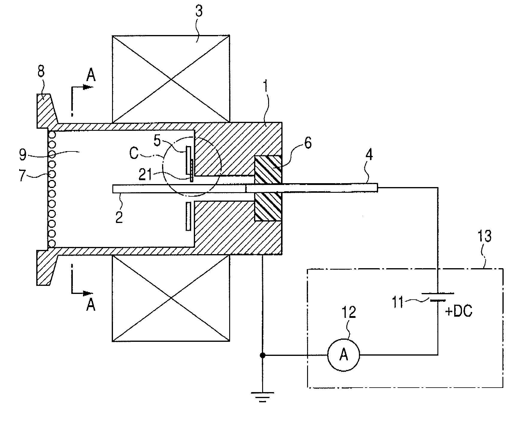
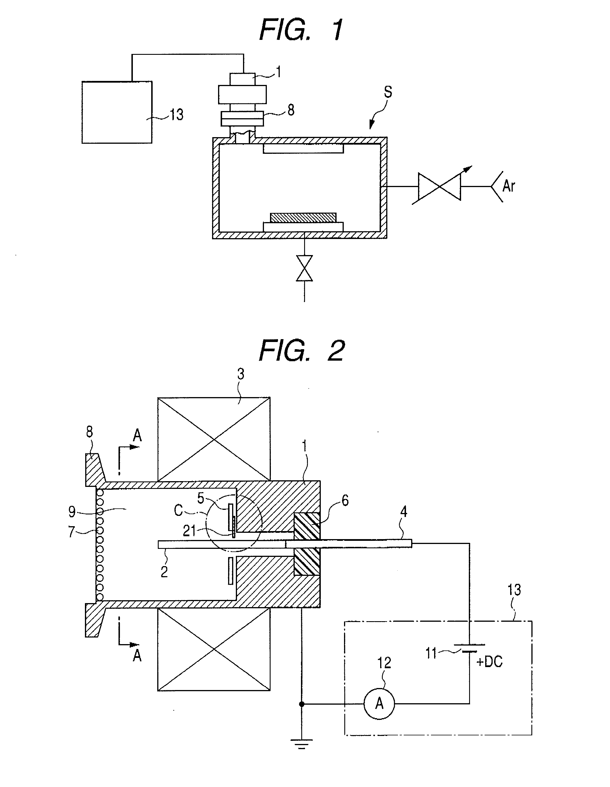
[0034]The cold cathode ionization vacuum gauge shown in FIG. 2 is an inverted magnetron vacuum gauge, and includes a gauge head chamber (cathode) 1 as a cathode, which is a metal member having a substantially cylindrical or tubular shape, and a rod-shaped anode 2 which is surrounded by a tubular discharge space 9 formed inside the gauge head chamber 1. As magnetic means for generating a magnetic field, an annular magnet 3 is placed along an outer periphery of the gauge head chamber (cathode) 1 in such a manner as to surround the gauge head chamber 1. A ferrite magnet is preferably used for the magnet 3. As will be described later, an auxiliary discharge starting electrode plate 5 is detachably attached to the inside of the gauge head chamber (cathode) 1.

[0035]Inside the gauge head chamber (cathode) 1, the anode 2 is connected to a current introducing rod 4. The current introducing rod 4 is connected to a vacuum gauge operation circuit 13 via an insulating stone 6 such as alumina cer...

second embodiment

[0058]FIG. 7A is a plan view showing a modification of the auxiliary discharge starting electrode plate according to the present invention, and FIG. 7B is a side view thereof. In FIGS. 7A and 7B, the same parts as those in FIGS. 3 to 5 are denoted by the same reference numerals. In this embodiment, a deformation absorbing plate 26 is attached the auxiliary discharge starting electrode plate 5 shown in FIGS. 2 to 5, and the fibrous member 20 is attached to this deformation absorbing plate 26 with the insulating material 23 interposed in between. An insulating adhesive such as a polyimide adhesive or an alumina adhesive is used for the insulating material 23 as mentioned above. Meanwhile, examples of the material of the deformation absorbing plate 26 include highly corrosion-resistant metals of, e.g., a stainless steel such as SUS304, nickel, a high melting point material, and the like.

[0059]In this embodiment, the insulating adhesive is applied to the deformation absorbing plate 26 p...

third embodiment

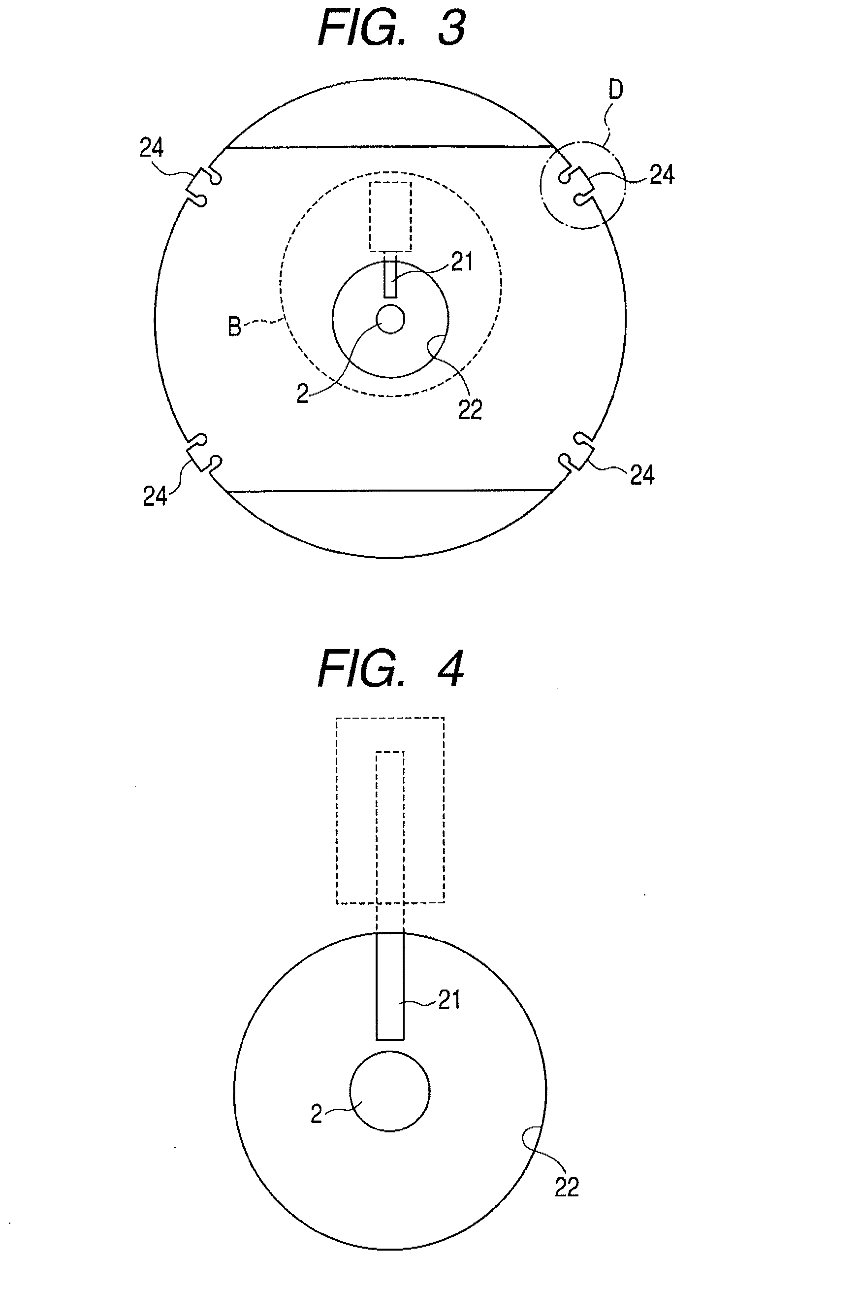
[0061]FIG. 8A is a plan view showing another modification of the auxiliary discharge starting electrode plate according to the present invention, and FIG. 8B is a side view thereof. In FIGS. 8A and 8B, the same parts as those in FIGS. 6 to 7B and so forth are denoted by the same reference numerals. In this embodiment, the protruding portion 21 of the auxiliary discharge starting electrode plate 5 shown in FIGS. 8A and 8B is placed off the center of the auxiliary discharge starting electrode plate 5 and closely to the anode 2. In this embodiment as well, it is possible to achieve a similar effect to that when the protruding portion 21 faces the anode 2.


PUM

PropertyMeasurementUnit
distanceaaaaaaaaaa
distanceaaaaaaaaaa
thicknessaaaaaaaaaa

Abstract

The present invention provides a cold cathode ionization vacuum gauge, an auxiliary discharge starting electrode plate, and a vacuum processing apparatus which have simple configurations and, even after long-term-use, which allow discharge to be initiated in a short-period of time and also to be performed stably after the start of the discharge. A cold cathode ionization vacuum gauge according to one embodiment of the present invention includes: an anode; a gauge head chamber (cathode) placed in such a manner as to form a discharge space together with the anode; and a protruding configured so that, in voltage-application to the anode and the cathode, an electric field should be concentrated at the protruding portion to a larger extent than an electric field at the gauge head chamber is. The protruding portion is provided inside the discharge space in such a manner that the protruding portion has a floating potential.

Description

CROSS-REFERENCES TO RELATED APPLICATIONS[0001]This application claims the benefit of priority from Japanese Patent Application No. 2009-128893 filed May 28, 2009, the entire contents of which is incorporated herein by reference.BACKGROUND OF THE INVENTION[0002]1. Field of the Invention[0003]The present invention relates to a cold cathode ionization vacuum gauge, a vacuum processing apparatus using the same, and an auxiliary discharge starting electrode plate, and particularly relates to an inverted magnetron cold cathode ionization vacuum gauge.[0004]2. Description of the Related Art[0005]A cold cathode ionization vacuum gauge measures a gas pressure by initiating ionization of the gas through self discharge of an anode and a cathode. Cold cathode ionization vacuum gauges of a penning type, a magnetron type, and an inverted magnetron type have been known as conventional cold cathode ionization vacuum gauges (see Japanese Patent Application Publication No. Hei 10-19711). In particula...

Claims


Application Information

Patent Timeline
Patent Type & Authority Applications(United States)
IPC IPC(8): G01L21/30
CPCG01L21/34
Inventor KAWASAKI, YOHSUKE
Owner CANON ANELVA CORP
Why Eureka
Try Eureka