
Method for monitoring a subsoil zone, particularly during simulated fracturing operations

a subsoil zone and monitoring method technology, applied in seismology, geological measurements, transmission, etc., can solve the problems of complex installation, unsuitable for real-time subsoil monitoring, and inability to enable rapid data processing

Inactive Publication Date: 2010-12-02
CGGVERITAS SERVICES
View PDF14 Cites 26 Cited by
  • Summary
  • Abstract
  • Description
  • Claims
  • Application Information

AI Technical Summary

Benefits of technology

[0011]One embodiment of the invention is a monitoring method enabling rapid detection of a microseismic event.
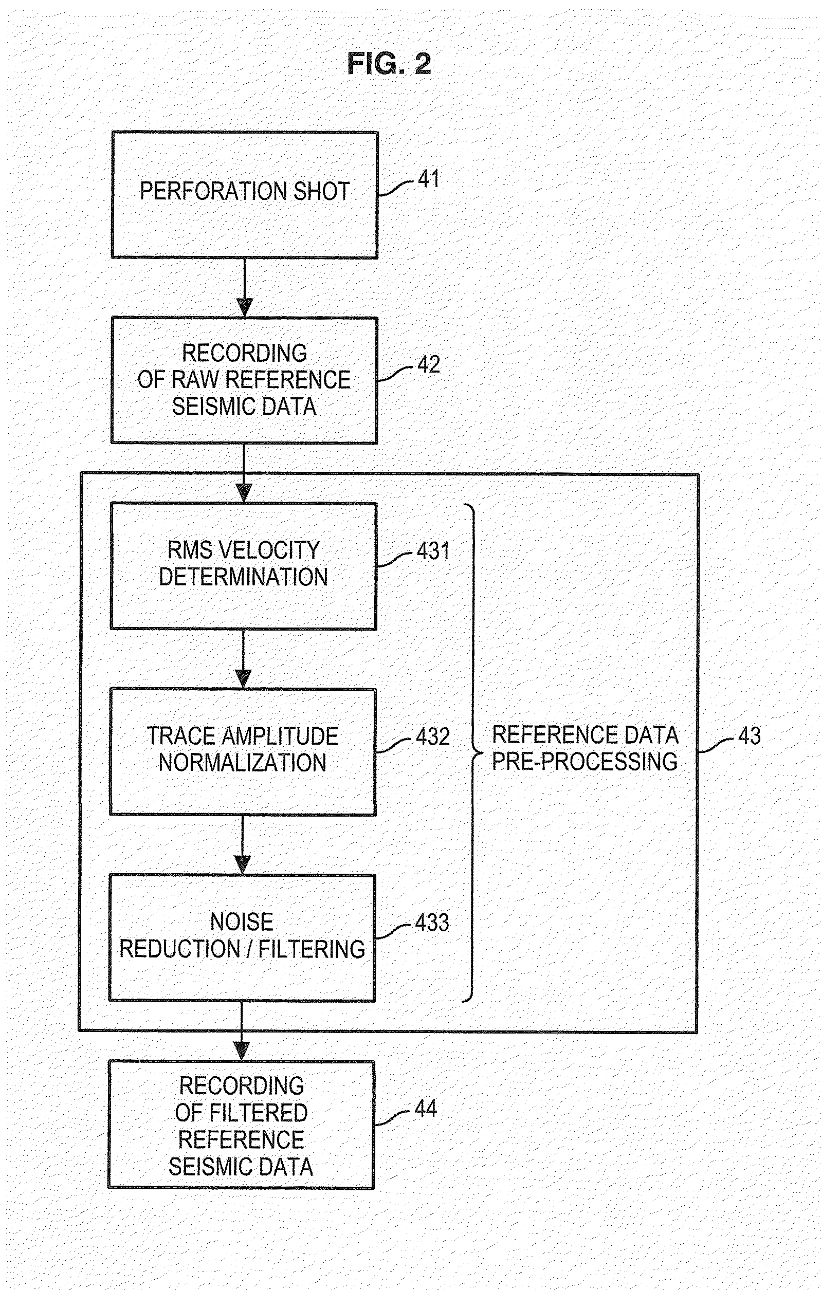
[0013]In some embodiments, the reference data generation step comprises the following sub-steps: activating an isotropic point source near the subsoil zone to be monitored; recording the data generated by said source; and, filtering said data to obtain a set of reference data. In some embodiments, the filtering step comprises the following: determining an RMS (Root Mean Square) velocity which maximizes the sum of the traces contained in the reference data; normalizing the amplitudes of the different traces to compensate for the differences in amplitudes between traces due to differences in source-receiver distance; and, filtering the normalized data to reduce noise contained therein.
[0020]The method of the present invention offer the advantage of enabling real-time processing of the seismic data acquired.
[0023]In addition to the fact that it enables real-time processing, the method and device of the present invention uses a perforation shot in the well to generate reference seismic data. This offers the advantage of not requiring the use of a velocity model. Indeed, the seismic data acquired following a perforation shot serve somewhat to characterize the subsoil zone and replace the use of the velocity model.

Problems solved by technology

The monitoring method described in WO 2008 / 033797 does not enable rapid data processing, and is not suitable for real-time subsoil monitoring.
One drawback of the method of U.S. Pat. No. 7,391,675 is that it is necessary to install receivers inside a well, which complicates the installation and increases the cost.
In addition, if the receivers are installed in the injection well, the well tends to vibrate under the effect of this injection, which raises the noise level on the receivers positioned in this well.
It is not always possible to have access to another well.

Method used


Image

  • Method for monitoring a subsoil zone, particularly during simulated fracturing operations
  • Method for monitoring a subsoil zone, particularly during simulated fracturing operations
  • Method for monitoring a subsoil zone, particularly during simulated fracturing operations

Examples


Embodiment Construction

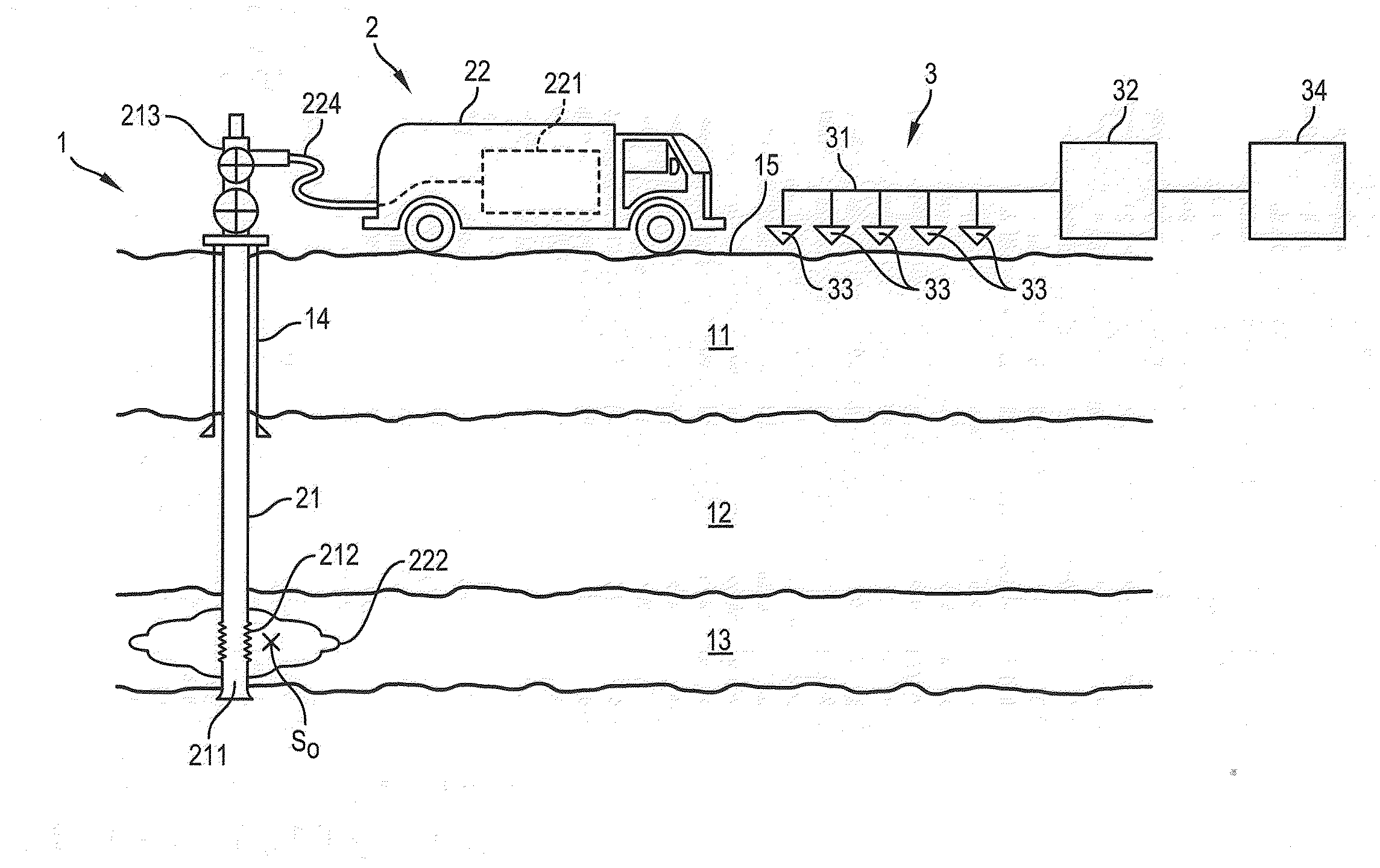
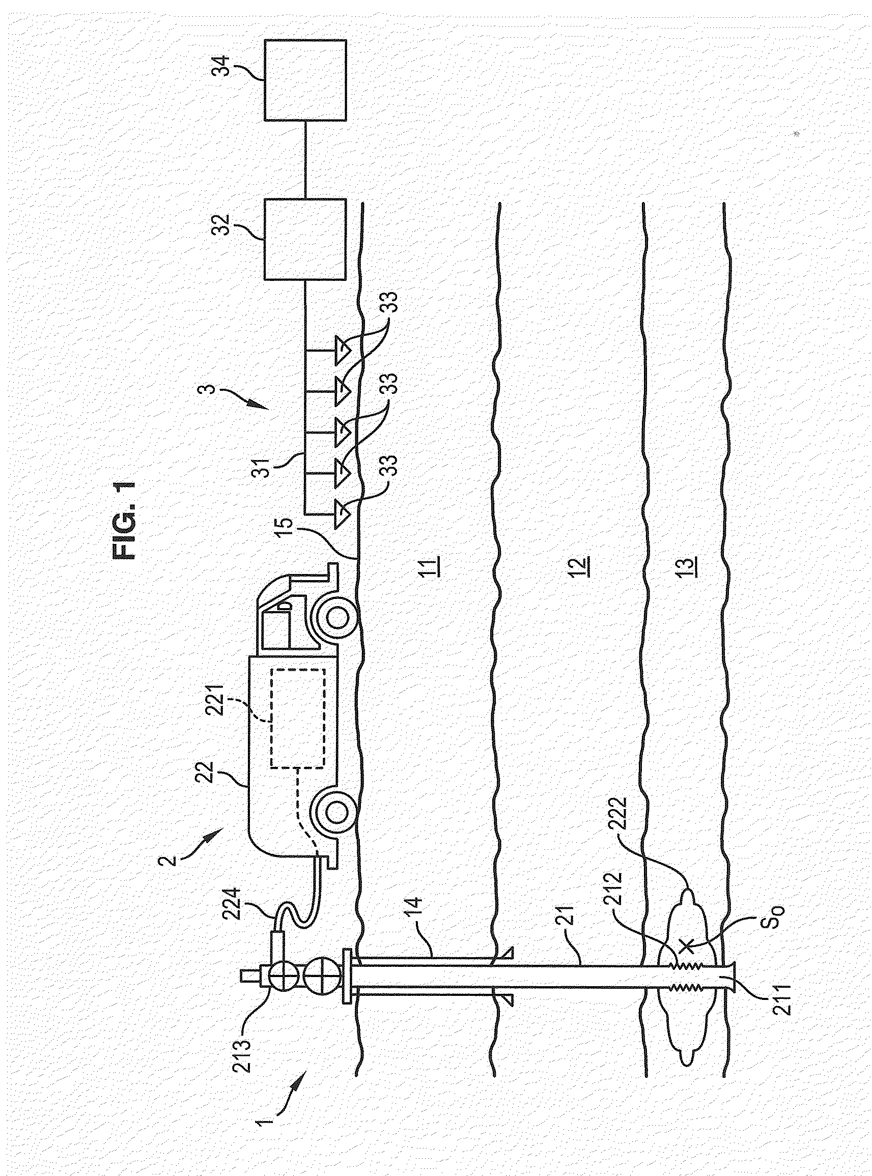
[0037]In FIG. 1, the installation is deployed on a hydrocarbon (gas or oil) production site 1. The site 1 comprises a subsoil zone, comprising geological layers 11, 12, 13. The layer 13 is a layer containing hydrocarbons. The site 1 comprises a well 14 drilled through the geological layers to the layer 13.

[0038]The installation also comprises a fracturing device 2 and a monitoring device 3. The fracturing device 2 comprises a fluid injection column 21 extending into the well 14 and a pumping unit 22 positioned on the surface 15 of the subsoil zone. The injection column 21 comprises a lower end 211 provided with openings 212 and an upper end 213 equipped with a well head 214 connected to the pumping unit 22.

[0039]The pumping unit 22 comprises a pump 221 suitable for injecting a high-pressure fracturing fluid 222 into the layer 13 via the injection column 22. The fracturing fluid typically consists of a mixture of a liquid (for example, water) and particles (for example, sand).

[0040]T...


PUM


Abstract

A method and device for monitoring a subsoil zone, wherein a plurality of receivers are arranged on a surface of the soil or near said surface, straight above a geological zone to be monitored, comprising the following steps: generating a set of reference seismic data; recording seismic data by means of said receivers; correlating the seismic data recorded with the reference seismic data; comparing each trace of the correlated data, with correlated traces located in a vicinity of said trace, in order to evaluate a similarity of each correlated trace with the adjacent correlated traces; and, detecting a microseismic event occurring in the subsoil zone by analysing said similarity. The method and device enables real-time monitoring.

Description

CROSS-REFERENCE TO RELATED APPLICATIONS[0001]This application claims priority, under 35 U.S.C. §119, to French Patent Application No. 0953487, filed on May 27, 2009.TECHNICAL FIELD[0002]The invention relates to a method for monitoring a subsoil zone by detecting microseismic events.[0003]It is applicable, for example, to method of monitoring stimulated fracturing performed in a well.BACKGROUND OF THE INVENTION[0004]Stimulated fracturing operations are intended to increase the productivity of a hydrocarbon reservoir working well. These operations consist of injecting a high-pressure fluid into a layer of the subsoil where the reservoir is located. The injection of the fluid produces microfractures in the layer. This technique makes it possible to increase the permeability of the reservoir by favoring hydrocarbon circulation via the microfractures to the well.[0005]However, these operations require continuous monitoring of the reservoir so as, on one hand, to monitor the progress of t...

Claims


Application Information

Patent Timeline
Patent Type & Authority Applications(United States)
IPC IPC(8): G01V1/36G01V1/28
CPCG01V1/366G01V2210/123G01V2210/324
Inventor MEUNIER, JULIEN
Owner CGGVERITAS SERVICES
Learn More