Wireless LAN device

Active Publication Date: 2010-12-02
BUFFALO CORP LTD
View PDF5 Cites 29 Cited by
  • Summary
  • Abstract
  • Description
  • Claims
  • Application Information

AI Technical Summary

Benefits of technology

[0020]Consequently, the wireless LAN device of the above aspect does not require the user to select between the operating mode in which the wireless LAN device operates as a wireless base station and the operating mode in which it operates as a wireless terminal. Namely, with the wireless LAN device of the above aspect, it is possible to automate the setting of its operating modes in which it operates as a wireless base station and as a wireless terminal, through switching of the operating modes. Because the wireless LAN device of the above aspect affords the automated setting of operating modes as described above, and thus avoids errors in setting operating modes introduced through human error, the device is especially effective for building a wireless LAN having a star topology composed of a single wireless base station (access point) and plural wireless terminals (clients).

Problems solved by technology

Configuration of the wireless LAN device, including switching of the operating mode, can be complicated and difficult for a user who is not experienced with wireless LAN devices.
Even a user familiar with wireless LAN devices may make mistakes in configuration.
On the other hand, in the case where the first network device lacks the function of a DHCP server the first wireless LAN device, despite having received a DHCPDISCOVER packet, cannot send back a DHCPOFFER packet to the wireless LAN device that sent the DHCPDISCOVER packet.
On the other hand, in the case where the second network device is not an access point (wireless base station), the second network device, despite having received a Probe Request packet, cannot send back a Probe Response packet to the wireless LAN device that sent the Probe Request packet.

Method used


Image

  • Wireless LAN device
  • Wireless LAN device
  • Wireless LAN device

Examples


embodiment 1

A. Embodiment 1

A1. Features of Network System

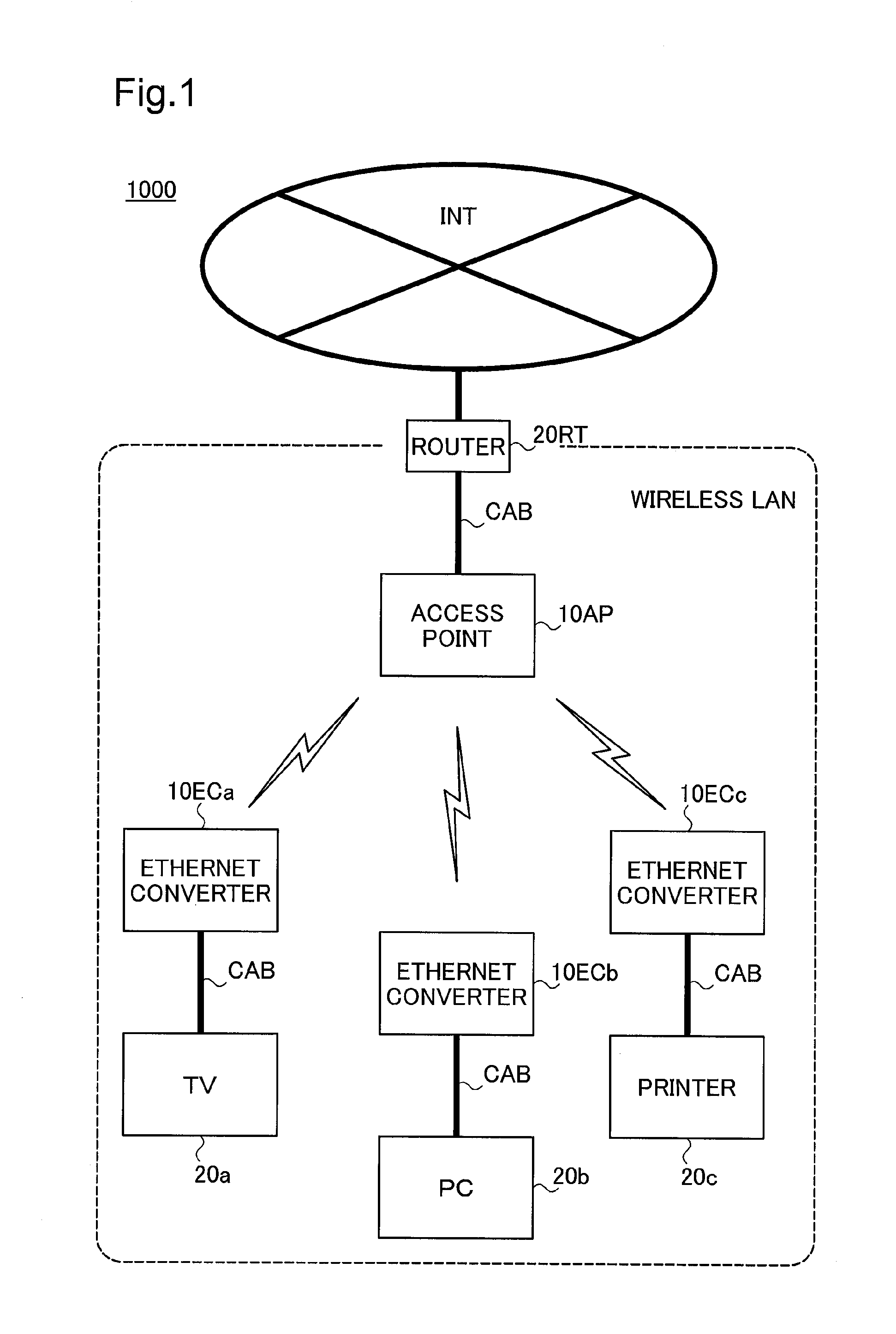
[0031]FIG. 1 depicts the general features of a network system 1000 implementing a wireless LAN device as an embodiment of the present invention. As illustrated, in the network system 1000 of the present embodiment, the Internet INT and a wireless LAN are connected through a router 20RT. The router 20RT has DHCP (Dynamic Host Configuration Protocol) server functionality, specifically, functionality whereby when the device receives a DCHPDISCOVER packet, as a response it returns a DHCPOFFER packet including an IP address to the sender of the DCHPDISCOVER packet, and assigns the IP address to it.

[0032]In the network system 1000, the wireless LAN includes an access point 10AP connected to the router 20RT by a LAN cable CAB; and several Ethernet converters 10ECa, 10ECb, 10ECc. The Ethernet converters 10ECa, 10ECb, 10ECc are respectively connected via LAN cables CAB to a television receiver 20a, a personal computer (PC) 20b, and a printer 20c. ...

embodiment 2

B. Embodiment 2

[0051]The hardware configurations of the network system 1000 and the hardware configurations of the wireless LAN device 10 of Embodiment 2 are identical to those in Embodiment 1. In Embodiment 2, the wireless LAN device 10 startup process differs from that of Embodiment 1. The wireless LAN device 10 startup process of Embodiment 2 is described below.

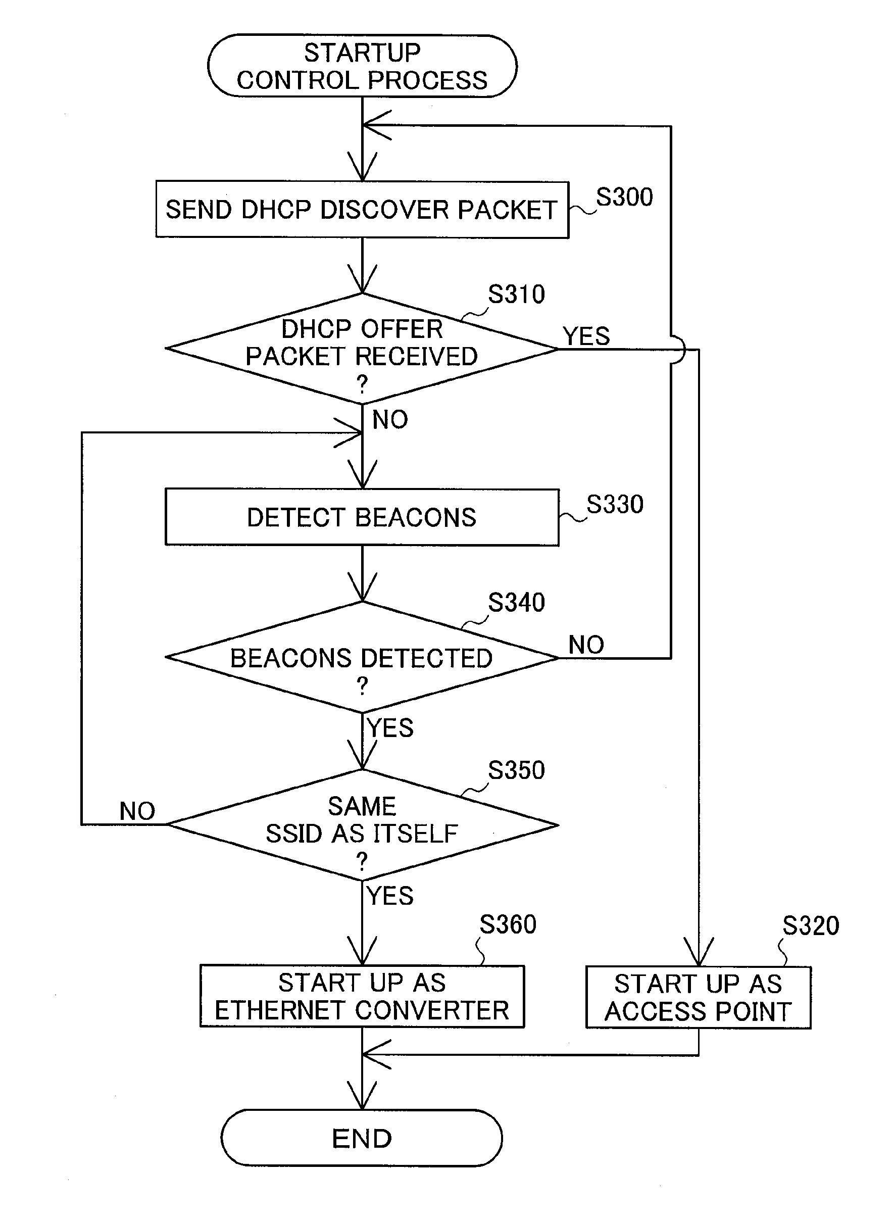
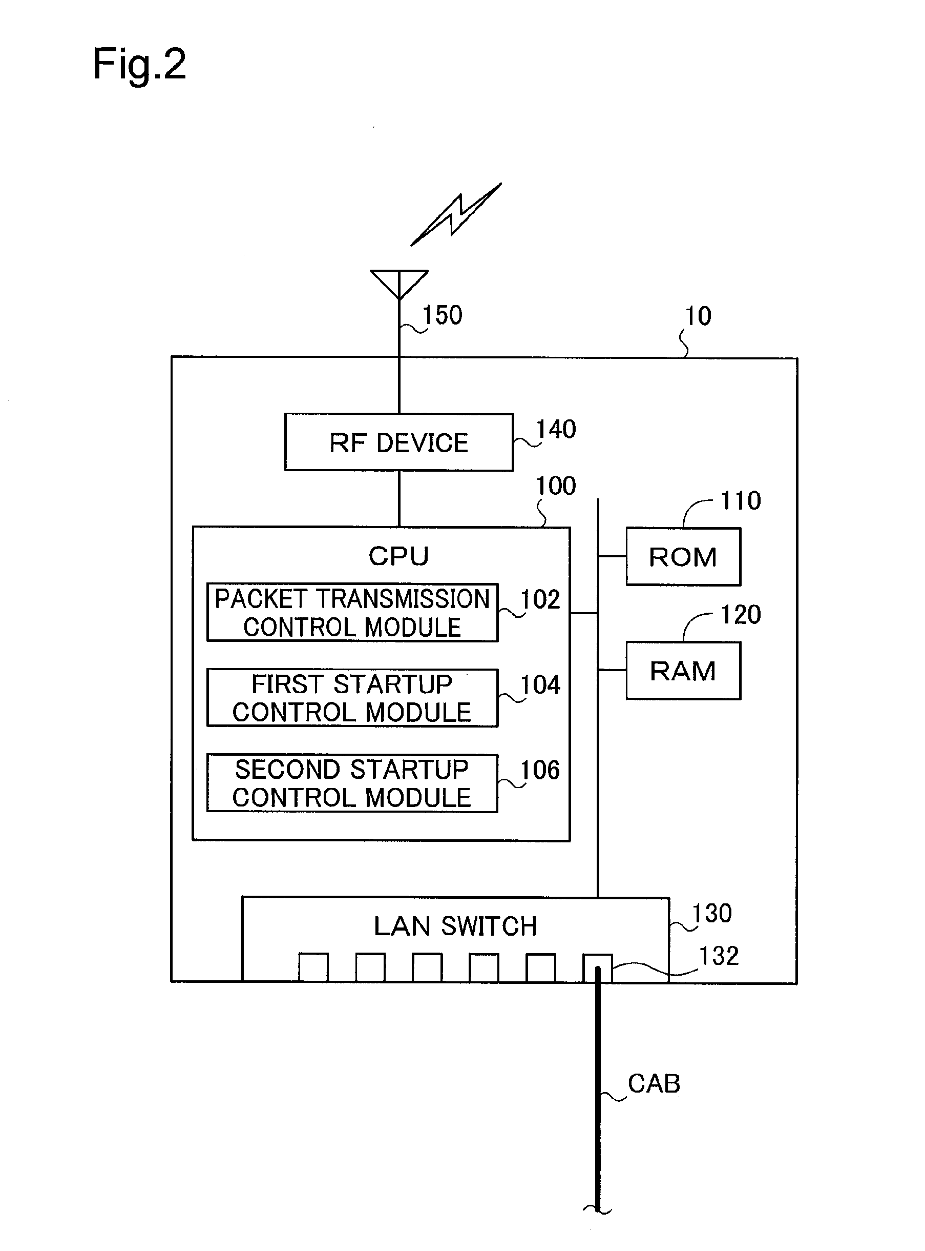
[0052]FIG. 4 is a flowchart depicting the flow of the startup control process of a wireless LAN device 10 of Embodiment 2. This process is one that the CPU 100 (the packet transmission control module 102, the first startup control module 104, and the second startup control module 106) provided to the wireless LAN device 10 executes at startup of the wireless LAN device 10.

[0053]First, when the wireless LAN device 10 is powered on, the packet transmission control module 102 sends a DHCPDISCOVER packet from the LAN switch 130 to the connected wired device 20 (Step S200). The CPU 100 then decides whether a DHCPOFFER packet wa...

embodiment 3

C. Embodiment 3

[0059]The hardware configurations of the network system 1000 of Embodiment 3 are identical to those in Embodiment 1. In Embodiment 3, the features of the wireless LAN device 10B and the startup control process differ from the features of the wireless LAN device 10 and the startup control process of Embodiment 1. The features of the wireless LAN device 10B and the startup control process of Embodiment 3 are described below.

[0060]FIG. 5 depicts the general features of a wireless LAN device 10B of Embodiment 3. As will be understood from a comparison of FIG. 5 and FIG. 2, the hardware features of the wireless LAN device 10B are identical to the hardware features of the wireless LAN device 10 in Embodiment 1. However, in the wireless LAN device 10B of Embodiment 3, the CPU 100 is provided with a second startup control module 106B in place of the second startup control module 106 in the wireless LAN device 10 of Embodiment 1, as one of the function blocks for carrying out ...


PUM


Abstract

The wireless LAN device 10 includes a packet transmission controller 102 having the function of transmitting a DHCPDISCOVER packet from a LAN switch 130 to wired devices and the function of causing an RF device to transmit a Probe Request packet to other wireless LAN devices through an antenna 150; a first operation controller 104 that can set the wireless LAN device 10 in the operating mode where the wireless LAN device 10 can operate as an access point, when the wireless LAN device 10 receives DCHPOFFER packet; and a second operation controller 106 that can set the wireless LAN device 10 in the operating mode where the wireless LAN device 10 can operate as a client, when the wireless LAN device 10 receives a Probe Response packet.

Description

1. TECHNICAL FIELD[0001]The present invention relates to a wireless LAN device.[0002]The entire disclosure of Japanese patent application No. 2009-130254, of BUFFALO Inc. is hereby incorporated by reference into this document.2. RELATED ART[0003]As the Internet has grown, there has been an associated expansion in number of various network devices connectable to networks such as LANs (Local Area Networks). Such network devices are available as wired network devices for wired connection to a network, and wireless network devices that connect wirelessly to a network.[0004]In recent years, wireless LAN devices that relay communications between wired network devices and wireless network devices have also become widespread. Such wireless LAN devices have a wired communication section for communication with wired network devices, and a wireless communication section for communication with wireless network devices. Examples of such wireless LAN devices are an access point (bridge) that func...

Claims


Application Information

Patent Timeline
IPC IPC(8): H04B7/14H04B1/3822H04B1/40H04W84/12H04W84/20
CPCH04L29/12226H04L61/2015H04W8/005H04W84/12H04W88/06H04L61/5014
Inventor TAMURA, NOBUHIROINADA, TETSUYA
Owner BUFFALO CORP LTD
Why Eureka
Try Eureka