Apparatus and method using hydrogen pressure in fuel cell electric vehicle

a technology of hydrogen pressure and electric vehicle, which is applied in the field of system and method for extracting energy from pressurized hydrogen, can solve the problems of power usage and complexity of the various electrical systems of automobiles, waste of pressure energy, and loss of energy (wasted), and achieves increased vehicle torque, more hydrogen flow, and high torque

Inactive Publication Date: 2010-12-02
GM GLOBAL TECH OPERATIONS LLC
View PDF8 Cites 20 Cited by
  • Summary
  • Abstract
  • Description
  • Claims
  • Application Information

AI Technical Summary

Benefits of technology

[0033]This method of charging the battery 114 of an electric vehicle uses waste heat from at least one of fuel cells 106, a electrical power converter 104, propulsion power converters 118, and other vehicle heat sources to heat expanding hydrogen that is converted to mechanical energy for driving a generator 108 to provide a multi-phase voltage that is converted to a current for charging the battery. The electrical power converter 110 regulates the flow of hydrogen. If the demand for power is low (fuel cell 106 requesting low hydrogen flow), the shaft 128 will rotate at a low speed since the electrical power converter control system commands higher torque on the generator. Once the fuel cell 106 demands more hydrogen flow (increased vehicle torque or speed request), the electrical power converter control system 110 reduces the torque command, thus increasing the speed on the shaft 128 and allowing more hydrogen to flow through the heat exchanger and air engine 104. Therefore, the heat exchanger and air engine 104 not only extracts pressure energy, it also performs flow regulation that is normally performed by a separate flow regulator valve. In this way, the heat exchanger and air engine 104 effectively extracts energy and performs a flow regulation.

Problems solved by technology

One of the changes involves the power usage and complexity of the various electrical systems within automobiles, particularly alternative fuel vehicles, such as hybrid, electric, and fuel cell vehicles.
However, energy is lost (wasted) when converted from a high pressure to the lower pressure for supplying the fuel cell.
Typically, known systems use a flow regulator and injectors, with pressure energy being wasted.

Method used


Image

  • Apparatus and method using hydrogen pressure in fuel cell electric vehicle
  • Apparatus and method using hydrogen pressure in fuel cell electric vehicle
  • Apparatus and method using hydrogen pressure in fuel cell electric vehicle

Examples


Embodiment Construction

[0016]The following detailed description of the invention is merely exemplary in nature and is not intended to limit the invention or the application and uses of the invention. Furthermore, there is no intention to be bound by any expressed or implied theory presented in the preceding technical field, background, brief summary or the following detailed description.

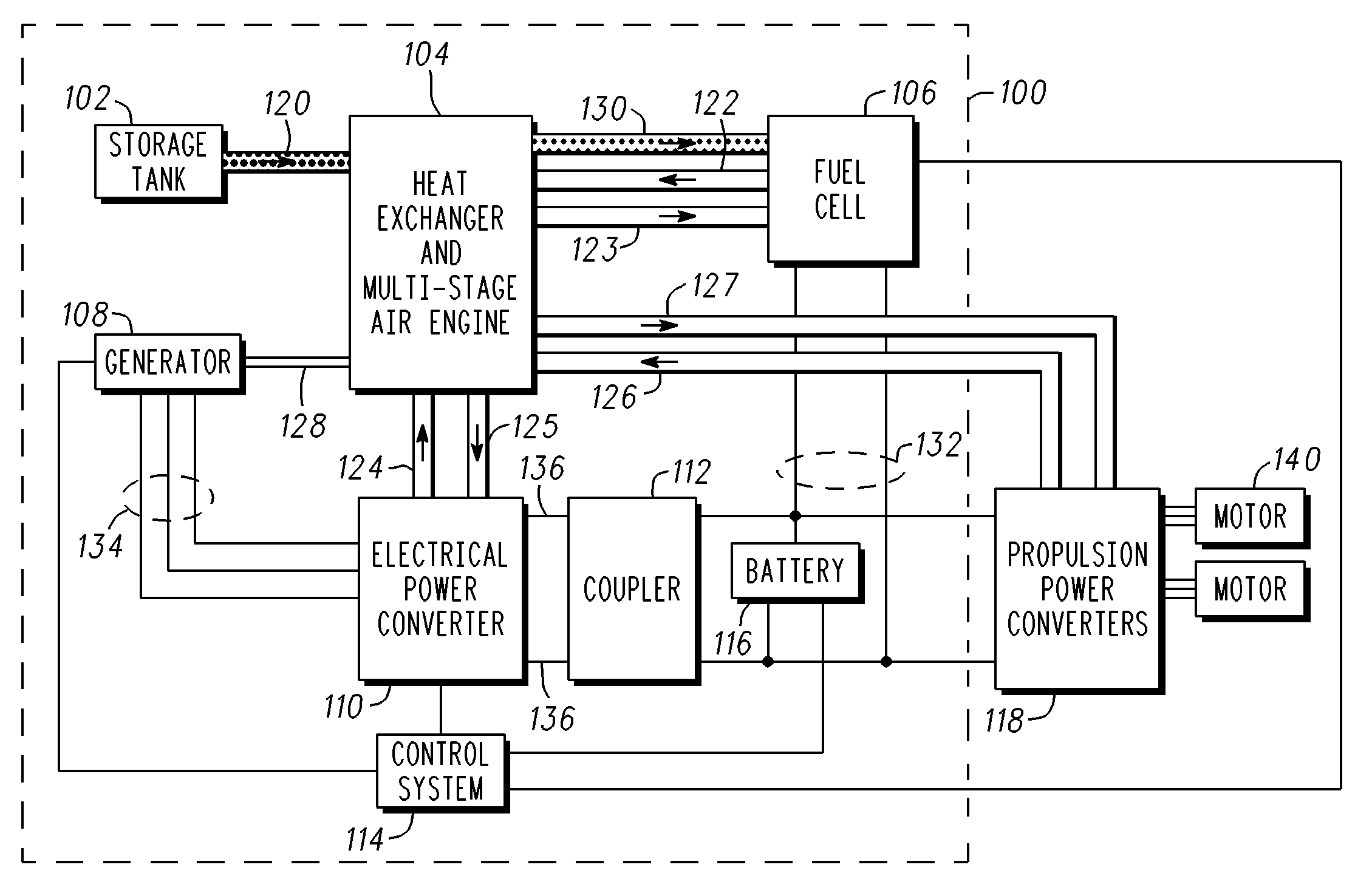
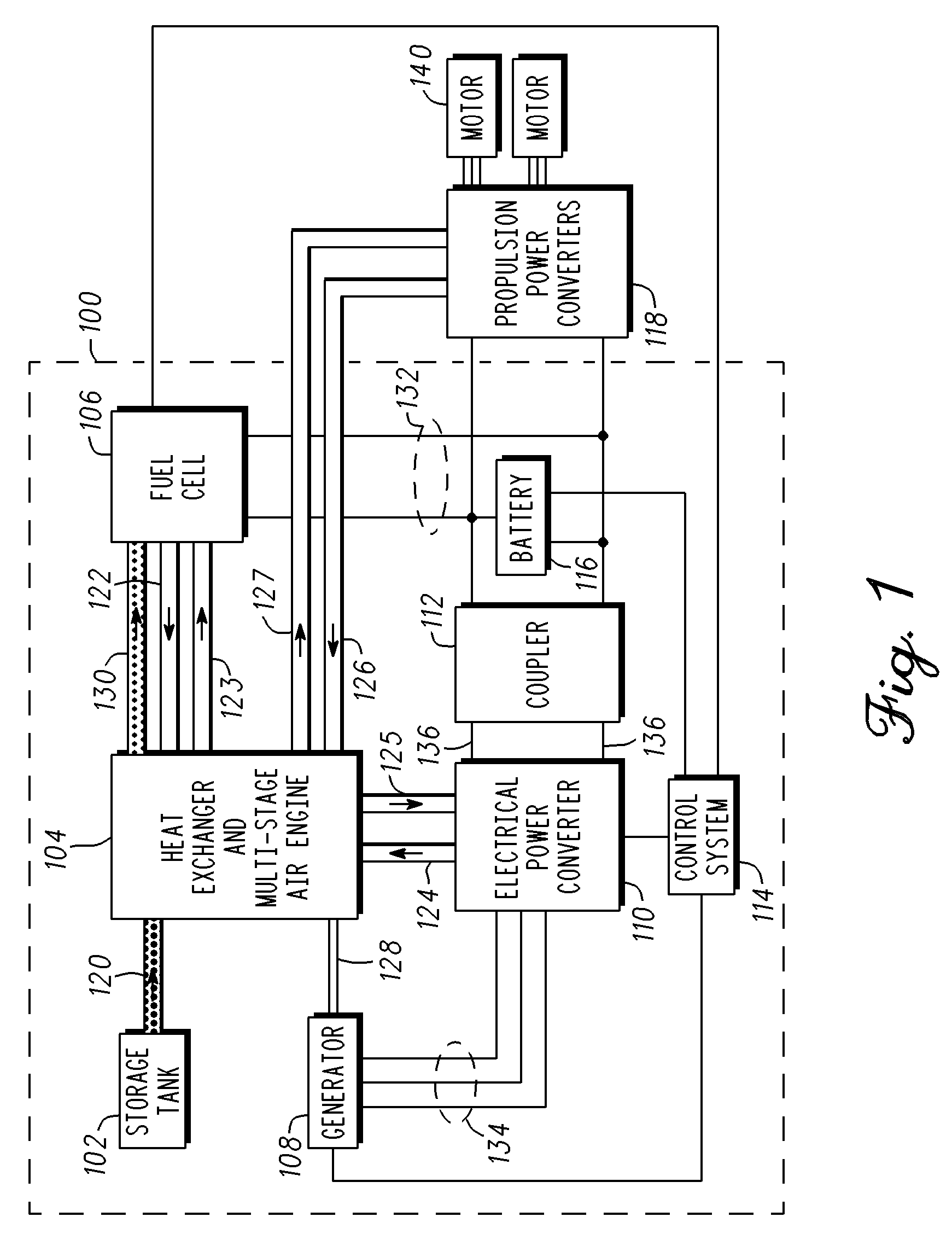
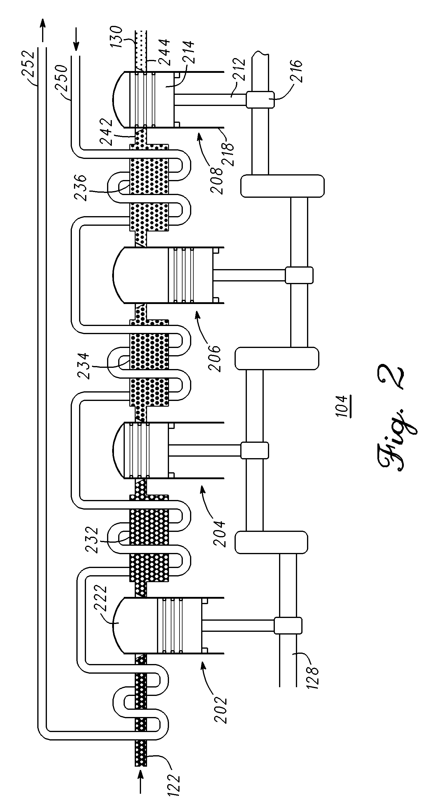
[0017]A system and method for extracting pressure energy and regulating hydrogen flow reuses waste heat to heat hydrogen during expansion when released from pressurized storage to increase range / distance of an electric vehicle. Heat is provided to the expanding hydrogen which drives a multi-stage “air” (hydrogen powered) engine and thus a generator for providing electricity to charge the electric vehicle's battery. It should be understood that “air” is used to describe a type of engine, and is not limited to using air (a combination mainly of oxygen and nitrogen gases) as popularly defined. The term “air” could include any...


PUM

PropertyMeasurementUnit
pressureaaaaaaaaaa
absolute pressureaaaaaaaaaa

Abstract

A hydrogen fuel cell system (100) for charging a battery (116) of an electric vehicle, includes at least one tank (102) for storing hydrogen under pressure. A combined heat exchanger and air engine (104) expands the pressurized hydrogen and converts the expanding hydrogen into mechanical energy. A plurality of fuel cells (106) receive the expanded hydrogen for supplying heat to the heat exchanger and air engine (104) and supplying a first current for charging the battery (116). A generator (108) generates a multi-phase voltage in response to the mechanical energy. A electrical power converter (110) responsive to the multi-phase voltage provides a second current for charging the battery (116).

Description

FIELD OF THE INVENTION[0001]The present invention generally relates to a fuel cell system for charging a battery of an electric vehicle, and more particularly relates to a system and method for extracting energy from pressurized hydrogen.BACKGROUND OF THE INVENTION[0002]In recent years, advances in technology, as well as environmental concerns and ever evolving tastes in style, have led to substantial changes in the design of automobiles. One of the changes involves the power usage and complexity of the various electrical systems within automobiles, particularly alternative fuel vehicles, such as hybrid, electric, and fuel cell vehicles. Such vehicles often use two separate voltage sources, for example, a battery and a fuel cell, to power the electric motors that drive the wheels.[0003]In July 2006 there were between 60,000 and 76,000 battery powered vehicles in use in the United States, increasing to an estimated over 100,000 battery powered vehicles in use today. Typically, one or...

Claims


Application Information

Patent Timeline
Patent Type & Authority Applications(United States)
IPC IPC(8): H01M8/04F02B63/00
CPCF01B1/02F01B17/02H01M8/04067H01M8/04089H01M2250/20H01M2250/402H01M2250/407Y02B90/12Y02E60/563Y02T90/32Y02B90/10Y02E60/50Y02T90/40
Inventor MAJAROV, KONSTANTIN S.O'MEARA, THOMAS P.
Owner GM GLOBAL TECH OPERATIONS LLC
Why Eureka
Try Eureka