
Leads for selective sensing and virtual electrodes

a selective sensing and electrode technology, applied in the field of electrodes, can solve problems such as side effects, contractile and electrical dysfunction,

Active Publication Date: 2010-12-02
MEDTRONIC INC
View PDF18 Cites 28 Cited by
  • Summary
  • Abstract
  • Description
  • Claims
  • Application Information

AI Technical Summary

Benefits of technology

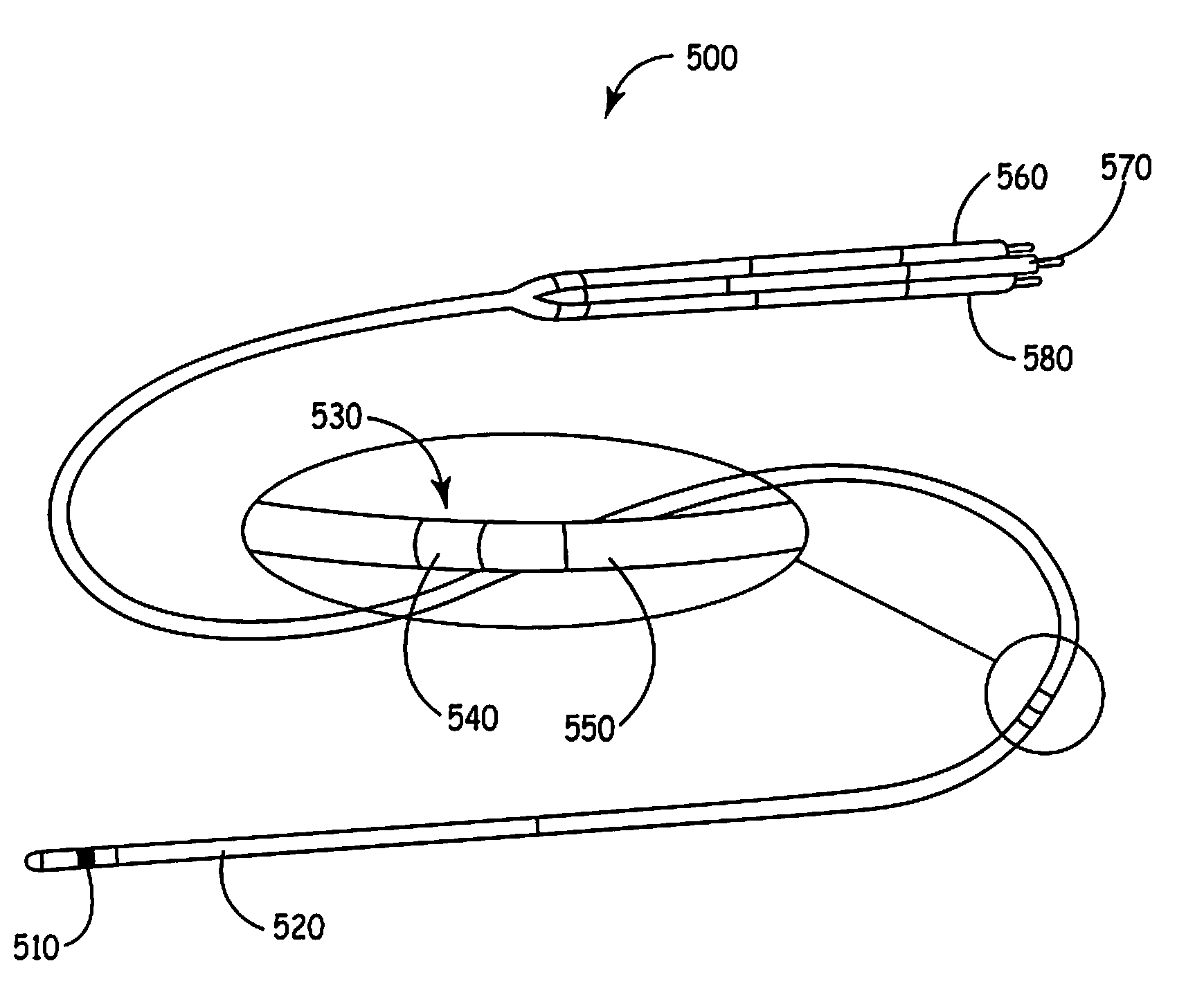
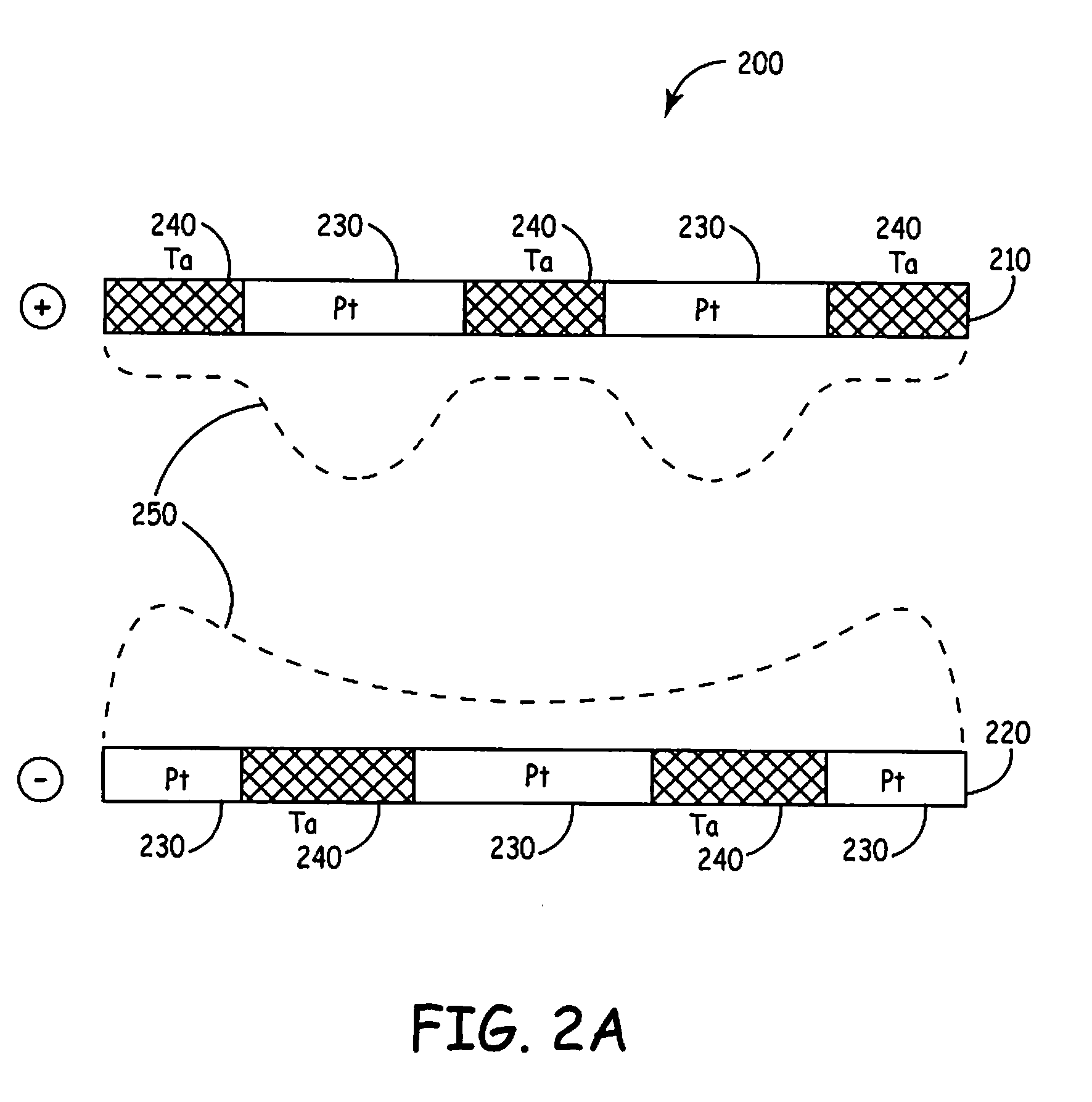
[0056]The present technology affords several benefits and advantages. The present systems and methods improve leads and electrodes by providing rectifying coatings to selectively sense with portions of an electrode coil, while pulsing with a larger contact area, and can further allow the creation of complex defibrillation fields, including virtual electrodes. The present electrodes and leads may reduce the chance of administering inappropriate defibrillation shocks. For example, one advantage of the present electrode and lead configurations is that single chamber pacing / defibrillation is combined with dual chamber sensing of atrial and ventricular signals. As a result, inappropriate detection of ventricular tachyarrhythmia may be reduced and consequently the administration of inappropriate shock may be reduced. The present electrode and lead configurations may also be implemented as single pass VDD or DDD defibrillation leads, depending on the ability of the atrial sense rings to provide reliable atrial pacing. The present electrodes also overcome limitations of integrated bipolar electrodes that use the entire coil for shocking and sensing. In addition, an implantable lead having one of the present electrodes, for example having a Ta2O5 portion and a Pt / Ir portion, can take the place of a lead having separate electrodes for pulsing and sensing in any IMD using such leads. The present leads and electrodes therefore reduce complexity and may reduce the number of conductors and connections required in lead manufacture.

Problems solved by technology

For example, defibrillation may result in side effects, including both contractile and electrical dysfunctions.

Method used


Image

  • Leads for selective sensing and virtual electrodes
  • Leads for selective sensing and virtual electrodes
  • Leads for selective sensing and virtual electrodes

Examples


Embodiment Construction

[0015]The following description of technology is merely exemplary in nature of the subject matter, manufacture and use of one or more inventions, and is not intended to limit the scope, application, or uses of any specific invention claimed in this application or in such other applications as may be filed claiming priority to this application, or patents issuing therefrom. The following definitions and non-limiting guidelines must be considered in reviewing the description of the technology set forth herein.

[0016]The headings (such as “Introduction” and “Summary”) and sub-headings used herein are intended only for general organization of topics within the present disclosure, and are not intended to limit the disclosure of the technology or any aspect thereof. In particular, subject matter disclosed in the “Introduction” may include novel technology and may not constitute a recitation of prior art. Subject matter disclosed in the “Summary” is not an exhaustive or complete disclosure ...


PUM

PropertyMeasurementUnit
lengthaaaaaaaaaa
conductiveaaaaaaaaaa
electrical signalaaaaaaaaaa

Abstract

Selective sensing implantable medical leads include pulsing and sensing portions and pulsing and not sensing portion. Leads and electrodes may be used in defibrillation and as integrated bipolar defibrillation electrodes. An entire electrode can pass charge while a valve metal or valve metal oxide portion of the electrode prevents the entire electrode from sensing, effectively rejecting unwanted signals. Differential conduction pathways, due to the valve metal and / or oxides thereof, cause the portions of the electrodes to conduct differently when used anodically and cathodically. Complex intracardiac electrical gradient can be formed along with a number of virtual electrodes within the tissue. Reentrant loops can thereby be pinned following defibrillation shock.

Description

INTRODUCTION[0001]The present technology relates to leads and electrodes for sensing and pulsing, for example, implantable medical leads for coupling to an implantable medical device (IMD).[0002]A wide variety of IMDs are used in the human body. IMDs can be manufactured as discrete units that may be selected by a physician for a particular clinical use and coupled at implantation with one or more medical electrical leads. IMDs may include an implantable pulse generator (IPG) or a physiologic monitor, and particular examples include cardiac pacemakers, cardioverter / defibrillators, cochlear implants, muscle and nerve stimulators, and deep brain stimulators. Such devices often include signal processing and / or pulse generating circuitry powered by a battery and enclosed within a hermetically sealed enclosure or housing, which may be referred to as a “can.” The can is typically formed of a conductive and biocompatible metal, such as titanium, which is corrosion resistant when exposed to ...

Claims


Application Information

Patent Timeline
Patent Type & Authority Applications(United States)
IPC IPC(8): A61N1/05
CPCA61N1/0534A61N1/0541A61B5/042A61N1/0563A61N1/056A61B5/283
Inventor LASKE, TIMOTHY G.MARTINEZ, GONZALOMARSHALL, MARK T.
Owner MEDTRONIC INC
Learn More