
Luminescent composition, light source device, and display device

Inactive Publication Date: 2010-12-09
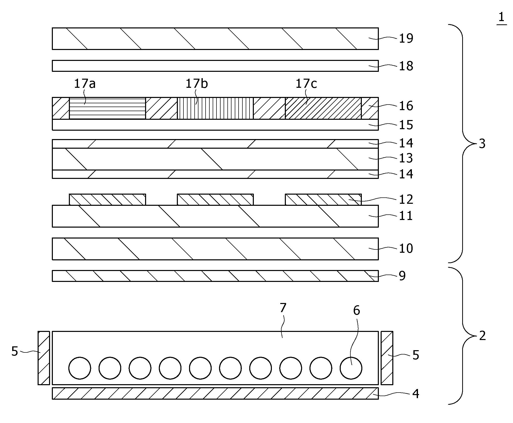
SONY CORP
View PDF3 Cites 10 Cited by
  • Summary
  • Abstract
  • Description
  • Claims
  • Application Information

AI Technical Summary

Benefits of technology

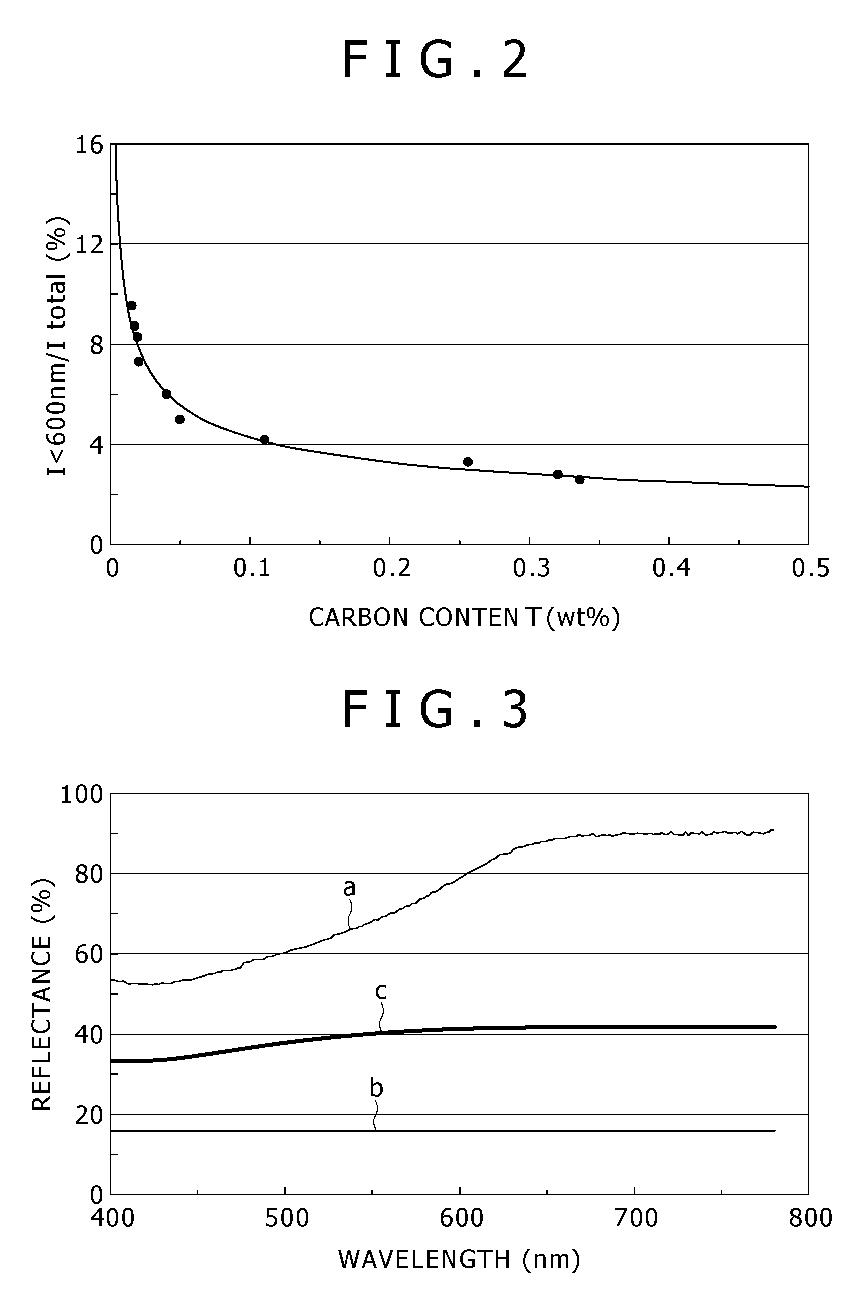
[0019]The luminescent composition according to the present invention contains carbon at a ratio of at least 0.05 weight % or higher. Therefore, both avoidance of the shift of the luminescence wavelength band of the phosphor toward the shorter wavelength side and suppression of color unevenness of the phosphor are achieved due to sufficient and uniform reduction of the oxygen that remains in the crystal structure of the phosphor.
[0020]In the light source device according to the present invention, the luminescent composition in the device contains carbon at a ratio of 0.05 weight % or higher. Therefore, enhancement in the characteristics of the light source device is achieved due to avoidance of the shift of the luminescence wavelength band of the phosphor toward the shorter wavelength side and suppression of color unevenness of the phosphor.
[0021]In the display device according to the present invention, the luminescent composition in the device contains carbon at a ratio of 0.05 weight % or higher. Therefore, enhancement in the characteristics of the display device is achieved due to avoidance of the shift of the luminescence wavelength band of the phosphor toward the shorter wavelength side and suppression of color unevenness of the phosphor.

Problems solved by technology

However, in a practical display device, a phenomenon occurs in which light of a certain color is output although the output thereof is unnecessary at this timing.
However, also regarding the light source device based on such a phosphor, the same problem relating to the above-described phenomenon has been pointed out.
However, oxygen is prone to remain in the red luminescent phosphors described in these documents.
Furthermore, such a problem in the phosphor becomes particularly serious as long as it is attempted to obtain the final phosphor not in a bulk (lump) state but in e.g. a granular state based on a large number of powders.
On the other hand, if the oxygen concentration is set lower than a certain value, the oxygen concentrations of the large number of granular phosphors easily become uneven and thus difference in the oxygen concentration arises among the individual granular phosphors.
This will cause color unevenness in the light source device and the display device.
That is, for the phosphors and inorganic substances described in Japanese Patent Laid-open No. 2006-8721 and Japanese Patent Laid-open No. 2005-235934, extreme reduction in the oxygen concentration of the granular phosphor causes this new problem.
Such a problem in the granular phosphor not only makes it difficult to manufacture the manufacturing light source device and the display device but also significantly deteriorates the characteristics of these devices.

Method used


Image

  • Luminescent composition, light source device, and display device
  • Luminescent composition, light source device, and display device
  • Luminescent composition, light source device, and display device

Examples


working example

[0045]A working example of the present invention will be described below.

[0046]Initially, a method for fabricating a luminescent composition according to the present working example will be specifically described below.

[0047]In the fabrication of the luminescent composition according to the present working example, initially Si3N4, AlN, Ca3N2, and EuN were mixed at a molar ratio of 1:3:0.985:0.045 and 10 g of this mixture was prepared through weighing.

[0048]Next, carbon powders were prepared through weighing separately from the previously-prepared 10 g mixture based on the total number of moles of Si3N4, AlN, Ca3N2, and EuN in this mixture so that an intermediate to be described later might have the predetermined carbon content finally. Specifically, the predetermined amount of carbon powders with respect to the total number of moles of the previously-prepared 10 g mixture was prepared through weighing (the predetermined amount was selected from the amounts obtained by multiplying t...


PUM


Abstract

The present invention is to provide a luminescent composition, a light source device, and a display device each having a phosphor for which both avoidance of the shift of the luminescence wavelength band toward the shorter wavelength side and suppression of color unevenness are achieved. A configuration is provided in which a luminescent composition having a phosphor with the same crystal structure as that of CaAlSiN3 contains carbon at a ratio of at least 0.05 weight % or higher.

Description

TECHNICAL FIELD[0001]The present invention relates to a luminescent composition containing a phosphor, a light source device having this luminescent composition, and a display device formed with this light source device.BACKGROUND ART[0002]In recent years, flat-type display devices referred to as so-called FPD (Flat Panel Display), such as liquid crystal displays, plasma displays, organic EL (Electro Luminescence) displays, are attracting attention.[0003]In these display devices, light of respective colors (e.g. red, green, and blue) finally output from the display plane is based on white light from a light source device provided in the form of e.g. a backlight and is output via an optical device including an optical modulation mechanism such as a liquid crystal. The white light supplied from the light source device is generally made as synthetic light of plural kinds of light having different center emission wavelengths.[0004]In such a display device, the color (e.g. one of red, gr...

Claims


Application Information

Patent Timeline
IPC IPC(8): H01J1/63C09K11/59
CPCC09K11/7734C09K11/0883C09K11/77348
Inventor TAMURA, TAKASHIHINO, TOMOKAZUKUSUNOKI, TSUNEOIGARASHI, TAKAHIRO
Owner SONY CORP
Learn More