
Magnetic field detection device

a detection device and magnetic field technology, applied in the direction of instruments, nmr measurements, therapy, etc., can solve the problems of unsuitable medical device use and unsuitable solutions, and achieve the effect of enhancing measurement accuracy and reducing power consumption

Active Publication Date: 2010-12-09
BIOTRONIK SE & CO KG
View PDF12 Cites 10 Cited by
  • Summary
  • Abstract
  • Description
  • Claims
  • Application Information

AI Technical Summary

Benefits of technology

[0008]The combination of a reed switch or a hall sensor or a GMR sensor for low field detection, and a MagFET sensor or hall sensor or a magnetotransistor for high field detection, allows a reduction of power consumption and an enhancement of measurement accuracy, because the different sensors can work, or more precisely measure, in a measurement range they are optimized for. The reed switch is a preferred element for low field detection for field strengths exceeding 1 mT, preferably in the range of 1 mT to 3 mT, while MagFET sensors or hall sensors or magnetotransistors are more suitable for high field detection in the order of a few tesla.

Problems solved by technology

Even the newly-presented so-called “MRI conditional” implants pose difficulties insofar as such devices have to be switched to a so-called “MRI safe” mode, which requires at least a consultation with a heart specialist before and after the MRI examination (if not requiring the presence of a heart specialist during the entire MRI examination).
These solutions still have power consumption which is unsuitable for use in a medical device.

Method used


Image

  • Magnetic field detection device
  • Magnetic field detection device
  • Magnetic field detection device

Examples


Embodiment Construction

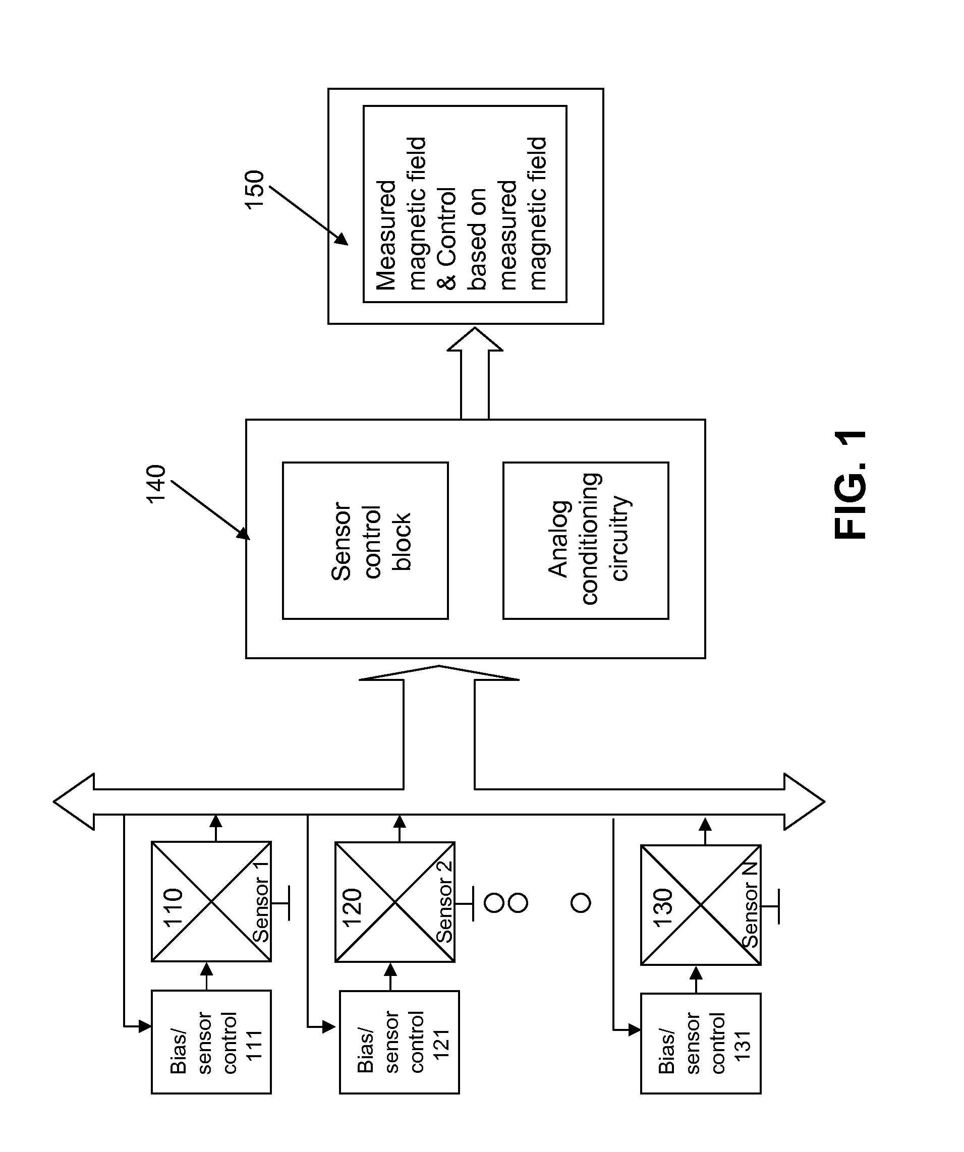
[0032]FIG. 1 shows a schematic view of a multi-sensor system in accordance with the invention. The different sensors 110, 120 and 130 are controlled via a bias / sensor control 111, 121 and 131, and are optimally biased for their working point. Therefore, energy consumption is minimized. The sensors are connected with the control block 140, comprising a sensor control block and an analog conditioning circuit, which delivers the field measurement and / or a control signal based on the measured magnetic field.

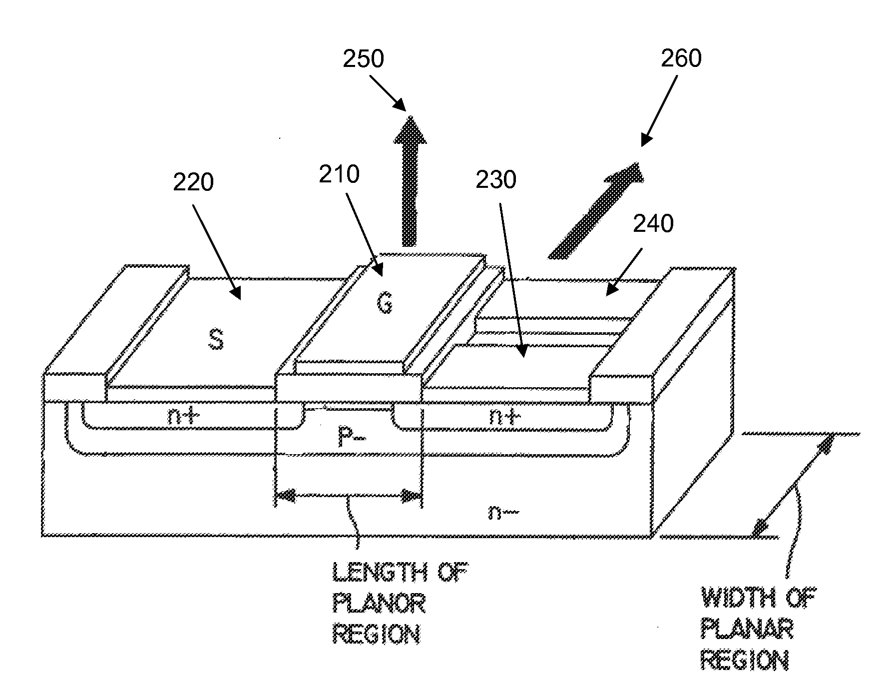
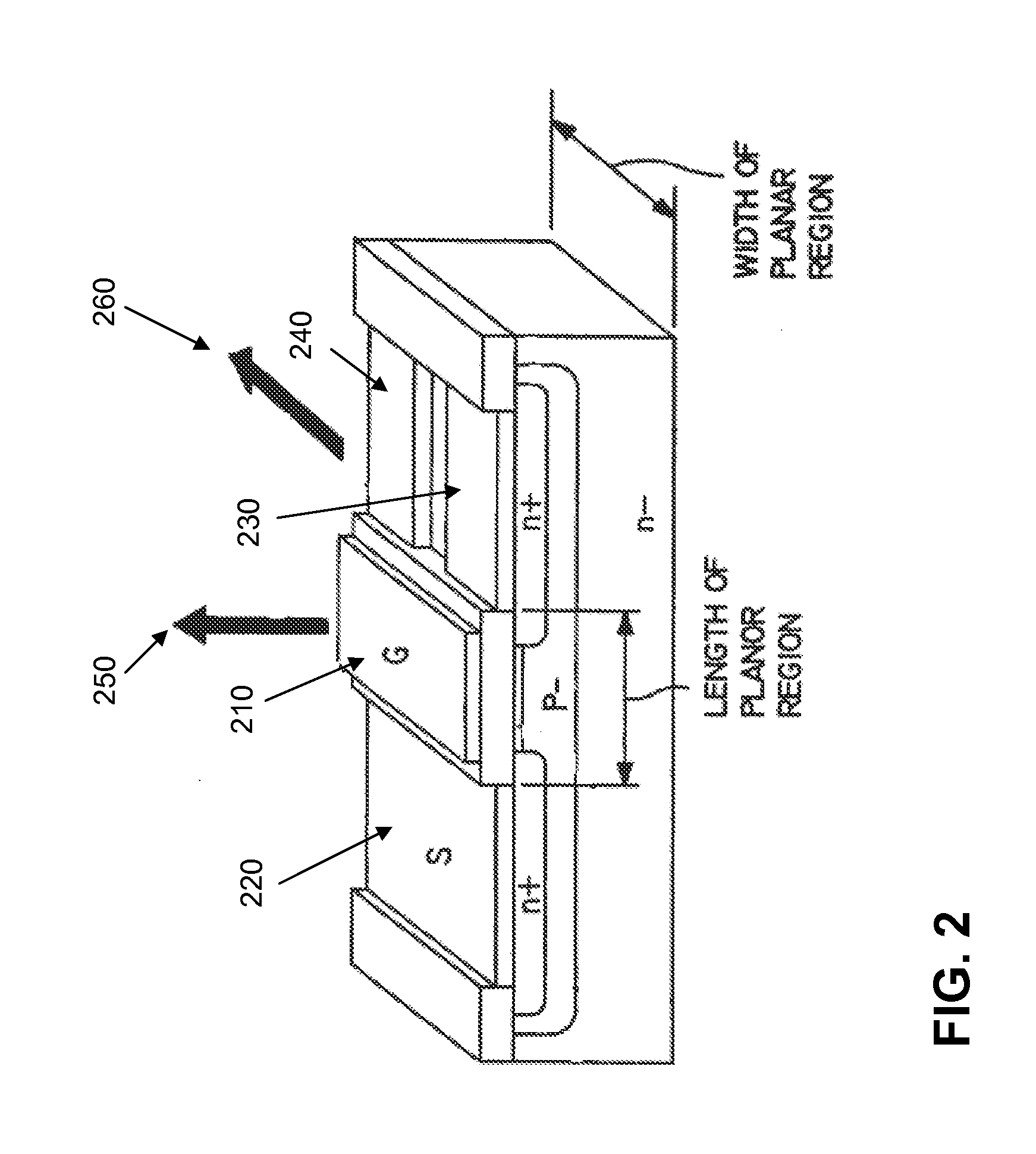
[0033]The assembly of a dual drain n-channel MagFET is schematically shown in a perspective view in FIG. 2. When operated in a magnetic field perpendicular to the channel or gate 210 of the electrical signal, such a field being identified with the arrow 250, the currents measured between the source 220 and drain 230 or 240 differ from each other because of the force (identified by arrow 260) affecting the charge carriers. The difference in the current is a measurement of the magnetic...


PUM


Abstract

A magnetic field sensor device suitable for use in an implantable medical device (such as a pacemaker, cardioverter / defibrillator, or cardiac resynchronization therapy device) is able to detect magnetic fields, such as the fields generated by a Magnetic Resonance Imaging (MRI) device, over a wide measurement range and to discriminate between different field strengths. Multiple sensors provided within the magnetic field sensor device are optimally biased to provide a power saving solution which is accurate enough for medical devices applications. The output of the magnetic field sensor device can be used to switch the implantable medical device to different operational modes, e.g., between programmable and “MRI safe” modes.

Description

CROSS-REFERENCE TO RELATED APPLICATIONS[0001]This application claims priority under 35 USC §119(e) to U.S. Provisional Patent Application 61 / 184,345 filed Jun. 5, 2009, the entirety of which is incorporated by reference herein.FIELD OF THE INVENTION[0002]The invention relates to an improved magnetic field detection device, and in particular to an improved magnetic field detection device for recognizing magnetic field strength over several magnitudes.BACKGROUND OF THE INVENTION[0003]Magnetic resonance imaging, further referred to as MRI, is of increasing relevance for modern diagnosis. Up to now active implanted medical devices (active IMDS), such as (but not restricted to) pacemakers, cardioverters / defibrillators, and cardiac resynchronization therapy devices, prevent effective utilization of MRI technology for diagnosis. Even the newly-presented so-called “MRI conditional” implants pose difficulties insofar as such devices have to be switched to a so-called “MRI safe” mode, which r...

Claims


Application Information

Patent Timeline
Patent Type & Authority Applications(United States)
IPC IPC(8): G01R33/44G01R33/06
CPCA61N1/37G01R33/0005A61N1/37223A61N1/3718
Inventor SHANKAR, IRANEDUNGADI, ASHOK
Owner BIOTRONIK SE & CO KG
Learn More