Turbine housing and method for producing a turbine housing

Inactive Publication Date: 2010-12-09
DAIMLER AG
View PDF10 Cites 14 Cited by
  • Summary
  • Abstract
  • Description
  • Claims
  • Application Information

AI Technical Summary

Benefits of technology

[0020]For improving the mechanical rigidity of the turbine housing and a beneficial material availability for the subsequent connection step, the first and the second partial housing are positioned by means of a suitable fit, for example a press fit or a transition fit.
[0021]In a further advantageous arrangement of the invention it is provided that the first and the second partial housing are connected to each other by means of a welding method, in particular a laser and or electron beam welding method. In this manner, the required properties with regard to exhaust gas tightness of the spiral channel, mechanical rigidity and minimum distortion are ensured even with a large serial production. The use of a welding method further enables a large automation degree, whereby corresponding time and cost advantages are achieved.
[0022]It has thereby further been shown to be advantageous if the first and the second partial housing are welded in the region of a weldable additional material, which is previously arranged in

Problems solved by technology

As turbine housings are subjected to frequent temperature ch

Method used


Image

  • Turbine housing and method for producing a turbine housing
  • Turbine housing and method for producing a turbine housing
  • Turbine housing and method for producing a turbine housing

Examples


Embodiment Construction

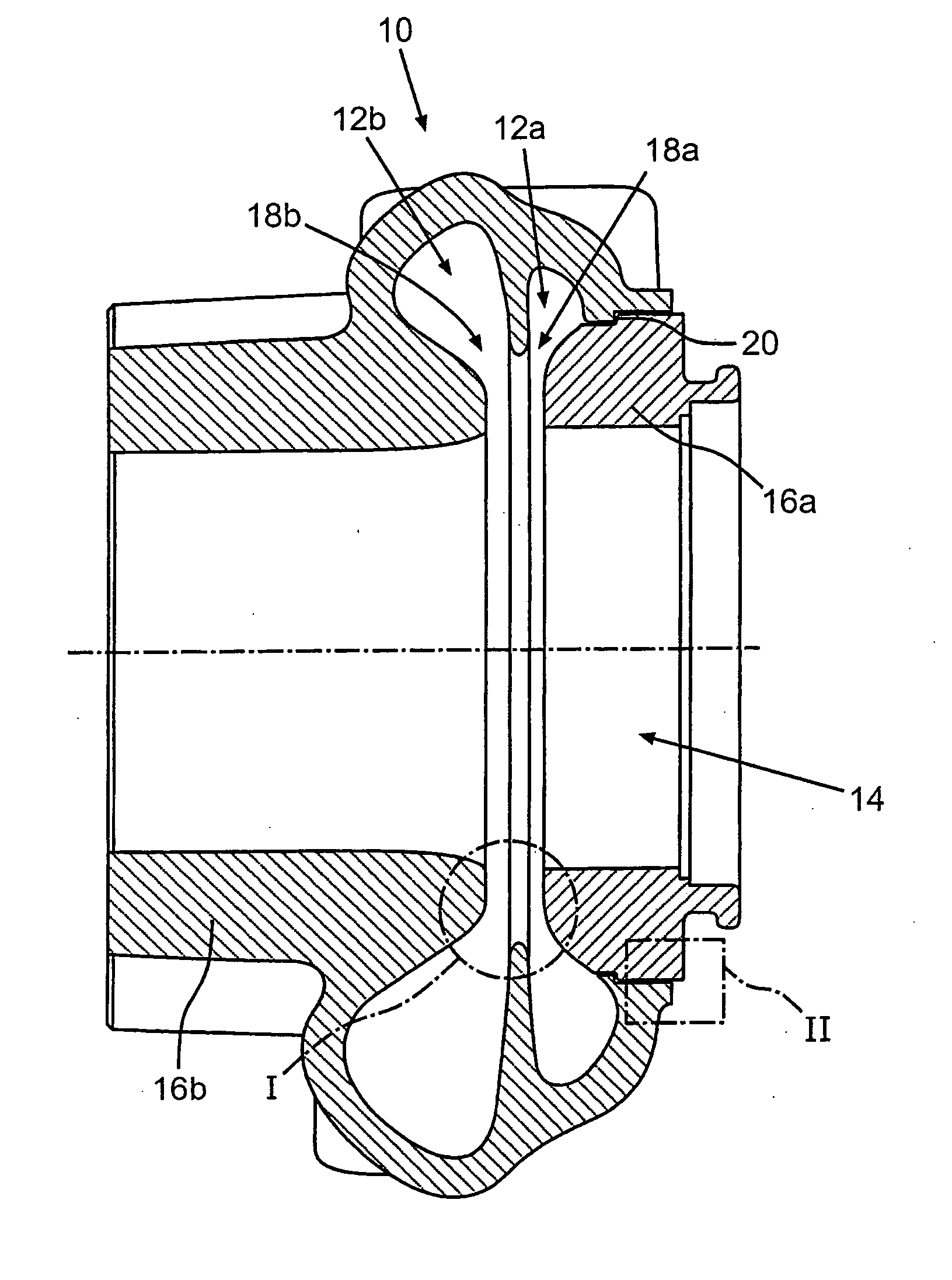
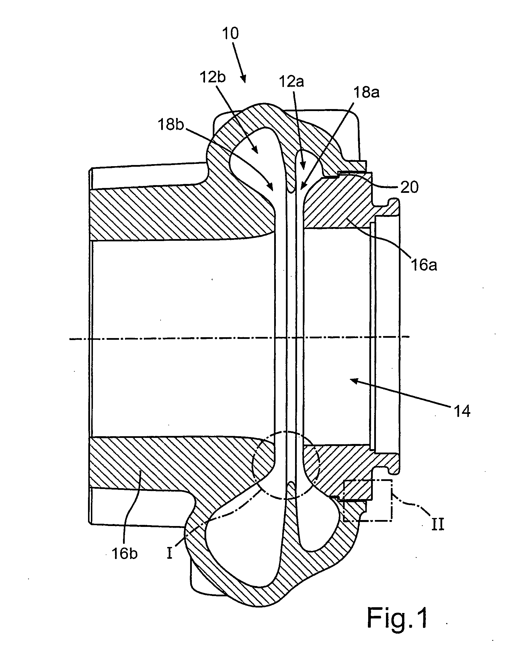
[0026]FIG. 1 shows in a cross-sectional view a turbine housing for an exhaust gas turbocharger of an internal combustion engine according to one embodiment,

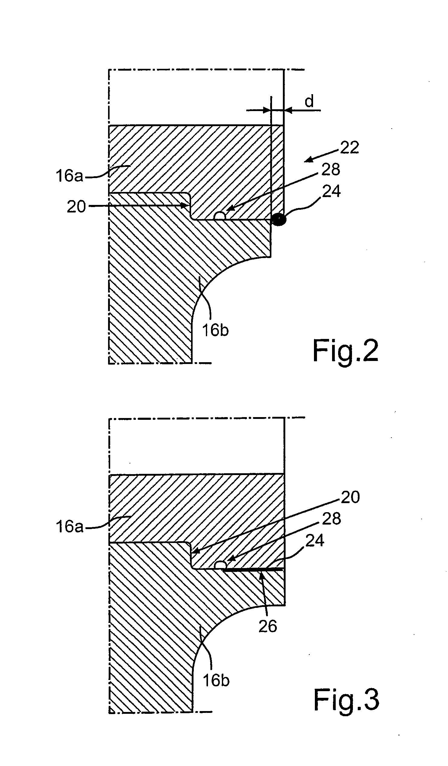
[0027]FIG. 2 shows the detail II shown in FIG. 1 in an enlarged view, and

[0028]FIG. 3 shows the detail II shown in FIG. 1 in an enlarged depiction in a second version.

DETAILED DESCRIPTION OF PARTICULAR EMBODIMENTS

[0029]FIG. 1 shows a turbine housing for an exhaust gas turbocharger of an internal combustion engine according to one embodiment in a sectional view. The turbine housing thereby comprises an exhaust gas guide region 10, that comprises two spiral channels 12a, 12b that can be coupled to two different exhaust paths of an exhaust tract and a reception chamber 14 arranged downstream of the spiral channels 12a, 12b for accommodating a turbine wheel. A first and a second partial housing 16a, 16b are thereby provided, which comprise complementary wall regions of the spiral channel 12a and are connected to each other while form...


PUM

PropertyMeasurementUnit
Timeaaaaaaaaaa
Contentaaaaaaaaaa
Thermal propertiesaaaaaaaaaa

Abstract

In a turbine housing, for an exhaust gas turbocharger of an internal combustion engine with an exhaust gas guide section which has at least one spiral channel that can be coupled to an exhaust path of an exhaust tract and a reception chamber for accommodating a turbine wheel arranged downstream of the at least one spiral channel, at least one first and one second partial housing are provided, which include complementary wall regions of the at least one spiral channel and which are joined so as to form the at least one spiral channel. Also, an exhaust gas turbocharger with such a turbine housing is provided and a method for producing such a turbine housing.

Description

[0001]This is a Continuation-In-Part application of pending international patent application PCT / EP2008 / 000866 filed Feb. 7, 2009 and claims the priority of German patent application 10 2008 008 856.0 filed Feb. 13, 2008.BACKGROUND OF THE INVENTION[0002]The invention relates to a turbine housing for an exhaust gas turbocharger of an internal combustion engine. The invention further relates to an exhaust gas turbocharger having a turbine housing and to a method for producing a turbine housing.[0003]Turbine housings for fluid flow machines, in particular for exhaust gas turbochargers of internal combustion engines are known from the state of the art and comprise an exhaust gas guide region, which has at least one spiral channel that can be coupled with an exhaust gas path of an exhaust tract and a reception chamber arranged downstream of the spiral channel. The reception chamber accommodates a turbine wheel, which is driven by the exhaust gas conducted through the exhaust gas guide re...

Claims


Application Information

Patent Timeline
IPC IPC(8): F04D29/44B23P15/04
CPCF01D9/026F05D2220/40Y10T29/4932F05D2230/234F05D2230/233
Inventor BOTSCH, SIEGFRIEDELSNER, CHRISTIANHERTWECK, GERNOTMULLER, MARKUSRAITHEL, SIMONSCHLEGL, MARTINSEUFFERT, JOHANNES
Owner DAIMLER AG
Why Eureka
Try Eureka