Dressing apparatus, dressing method, and polishing apparatus

a technology of dressing method and polishing apparatus, which is applied in the direction of grinding drive, grinding drive, manufacturing tools, etc., can solve the problems of reducing reducing the polishing speed (i.e., the removal rate), and reducing the size of the semiconductor device. , to achieve the effect of generating low pressing force and improving the operation rate of the polishing apparatus

Active Publication Date: 2010-12-09
EBARA CORP
View PDF13 Cites 33 Cited by
  • Summary
  • Abstract
  • Description
  • Claims
  • Application Information

AI Technical Summary

Benefits of technology

[0015]It is a second object of the present invention to provide a dressing apparatus capable of stably producing a low pressing force of the dresser disk.
[0027]According to the present invention, the load-measuring device, incorporated in the dresser drive shaft, can establish the relationship between the pressing force and the pressure of the gas within a very short period of time before or after the dressing operation or during the dressing operation. Therefore, it is not necessary to stop the operations of the polishing apparatus and as a result the operation rate of the polishing apparatus can be improved.
[0028]Further, according to the present invention, providing of the lifting mechanism enables setting of a large gas-pressure difference between two pressure chambers in the air cylinder. Therefore, operating zone of the air cylinder lies out of the dead zone (which is a zone where the piston does not operate in spite of a change in the differential pressure). Hence, the air cylinder can generate low pressing forces stably.

Problems solved by technology

Semiconductor devices become smaller and smaller in recent years, and device structures become more complicated.
Consequently, as polishing of the substrate is repeated, a polishing speed (i.e., a removal rate) is lowered and uneven polishing occurs.
In addition to the above-described problem, the dressing apparatus using the air cylinder entails the following drawback.
In such a dead zone where the air cylinder 136 does not operate, good dressing of the polishing pad 10 is not performed and as a result, stable polishing performance of the polishing pad 10 cannot be achieved.

Method used


Image

  • Dressing apparatus, dressing method, and polishing apparatus
  • Dressing apparatus, dressing method, and polishing apparatus
  • Dressing apparatus, dressing method, and polishing apparatus

Examples


first embodiment

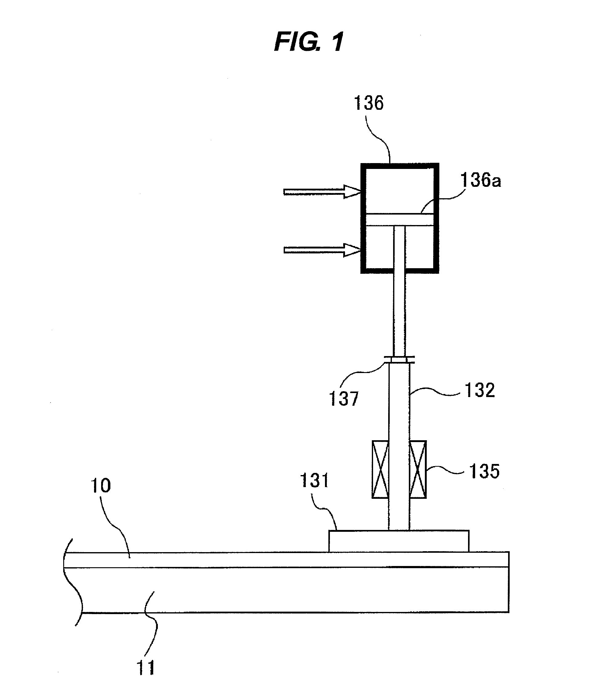
[0051]FIG. 3 is a schematic view showing the dressing unit 30 according to the present invention. As shown in FIG. 3, the dressing unit 30 includes an air cylinder (a pneumatic cylinder) 36 as a pressing mechanism for pressing the dresser disk 31 against the polishing pad 10 through the dresser drive shaft 32. The dresser drive shaft 32 is supported by a ball spline 35. This ball spline 35 is a linear motion guide which transmits a torque to the dresser drive shaft 32, while allowing a straight line motion of the dresser drive shaft 32 in a longitudinal direction thereof. The ball spline 35 is rotatably supported by bearings 48, which are fixedly mounted on a support base 49 secured to the dresser swing arm 33. Relative positions of the support base 49 and the ball spline 35 in a vertical direction with respect to the dresser swing arm 33 are fixed.

[0052]A motor (not shown) is coupled to the ball spline 35 and this motor causes the dresser disk 31 to rotate through the dresser drive...

second embodiment

[0068]FIG. 6 is a schematic view showing a modified example of the dressing unit according to the present invention. In this modified example, the spring 50 is located below the coupling 37. The spring stopper 51 is secured to the rotating section of the dresser drive shaft 32. A lower end of the spring 50 is secured to the ball spline 35. The spring 50, the ball spline 35, and the dresser drive shaft 32 are rotated in unison.

[0069]In the dressing unit shown in FIG. 5 and FIG. 6, the pressing force F of the dresser disk 31 against the polishing pad 10 is expressed as a resultant force of a downward force Fc[N] generated by the air cylinder 36, a weight mg[N] of the dresser assembly in its entirety, and an upward force Fb[N] generated by the spring 50. FIG. 7 is a graph showing a relationship between the pressure Pc of the air supplied to the upper pressure chamber of the air cylinder 36 and the pressing force F acting on the polishing pad 10. In FIG. 7, a vertical axis indicates the...

third embodiment

[0086]FIG. 9 is a schematic view showing a modified example of the dressing unit according to the present invention. In this modified example, the spring 50 is arranged below the coupling 37. The spring stopper 51 is secured to the rotating section of the dresser drive shaft 32, and the lower end of the spring 50 is secured to the ball spline 35. The spring 50, the ball spline 35, and the dresser drive shaft 32 are rotated in unison. In this example also, the difference ΔS (i.e., the amount of correction) between the pressing force F of the dresser disk 31 and the measurement value F′ of the load cell 45 is determined according to the same procedures as discussed above.

[0087]FIG. 10 is a schematic view showing the dressing unit according to a fourth embodiment of the present invention. Structures and operations of this embodiment, which will not be described below, are identical to those of the above-described second embodiment, and repetitive descriptions thereof will be omitted. A...


PUM

PropertyMeasurementUnit
pressure-aaaaaaaaaa
pressureaaaaaaaaaa
speedaaaaaaaaaa

Abstract

A dressing apparatus for use in a polishing apparatus for polishing a substrate to planarize a surface of the substrate is disclosed. The dressing apparatus includes a dresser disk, a dresser drive shaft coupled to the dresser disk, a pneumatic cylinder configured to press the dresser disk against the polishing pad through the dresser drive shaft, a pressure-measuring device configured to measure pressure of the gas supplied to the pneumatic cylinder, a load-measuring device configured to measure a load acting on the dresser drive shaft, and a pressure controller configured to control the pressure of the gas supplied to the pneumatic cylinder. The pressure controller is configured to establish a relationship between the pressure of the gas and a pressing force of the dresser disk against the polishing pad, based on measurement values of the pressure-measuring device and the load-measuring device.

Description

BACKGROUND OF THE INVENTION[0001]1. Field of the Invention[0002]The present invention relates to a dressing apparatus and a dressing method for dressing a polishing pad used in polishing of a substrate, such as a semiconductor wafer. More particularly, the present invention relates to a dressing apparatus and a dressing method used in a polishing apparatus for polishing the substrate to planarize a surface of the substrate. The present invention also relates to a polishing apparatus having such a dressing apparatus.[0003]2. Description of the Related Art[0004]Semiconductor devices become smaller and smaller in recent years, and device structures become more complicated. A surface planarization is an essential process in fabrication of the semiconductor devices. A typical technique used in the surface planarization is chemical mechanical polishing (CMP). In this chemical mechanical polishing, a substrate is brought into sliding contact with a polishing surface of a polishing pad, whi...

Claims


Application Information

Patent Timeline
Patent Type & Authority Applications(United States)
IPC IPC(8): B24B49/00B24B55/00B24B5/00B24B1/00B24B53/00B24B53/017B24B53/02H01L21/304
CPCB24B49/08B24B53/017B24B49/16
Inventor SHINOZAKI, HIROYUKI
Owner EBARA CORP
Why Eureka
Try Eureka