
Environmental electrical generator

a generator and environmental technology, applied in the direction of electric generator control, generator/motor, machine/engine, etc., can solve the problem of reducing the efficiency of the energy conversion system

Active Publication Date: 2010-12-16
SINGLE BUOY MOORINGS INC
View PDF9 Cites 34 Cited by
  • Summary
  • Abstract
  • Description
  • Claims
  • Application Information

AI Technical Summary

Benefits of technology

[0009]According to one preferred embodiment of the present invention, the SM sheets are wound, wrapped or rolled in the form of a tube of SM. The tube can be a continuous multilayer wound tube of several SM layers spaced in radial direction or a tube made out of combined segments, rings or tube parts, each acting as a variable capacitor. Capacitor electrodes lie against opposite faces of each of the segments. The tube parts or capacitors may be interconnected in tandem so to form a tube. Segmenting of the tube is also advantageous for fabrication, assembling and maintenance purposes.

Problems solved by technology

This can require AC / DC conversions and voltage step ups or step downs, which result in power losses that can greatly reduce the efficiency of the energy conversion system.

Method used


Image

  • Environmental electrical generator
  • Environmental electrical generator
  • Environmental electrical generator

Examples


Embodiment Construction

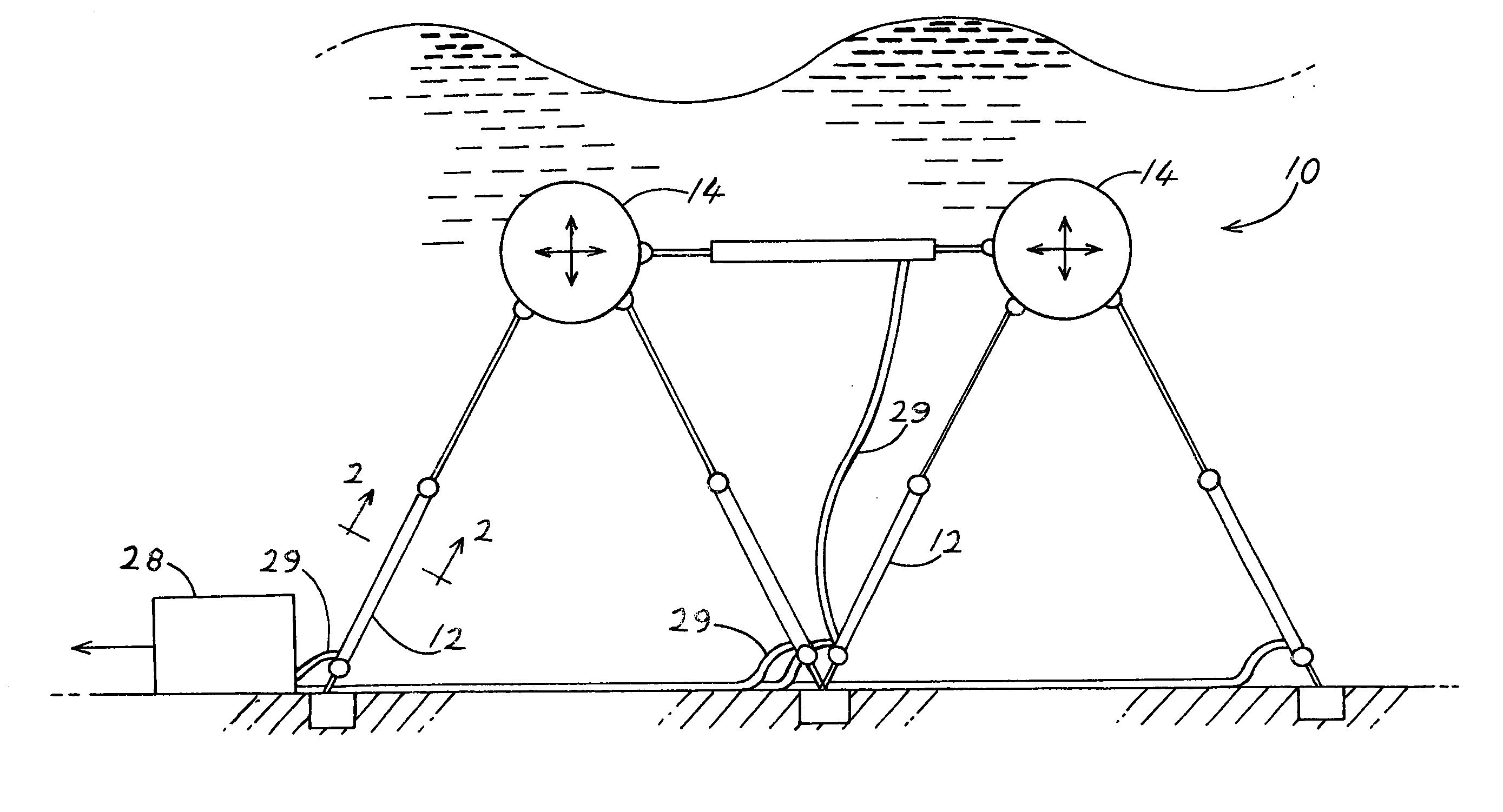
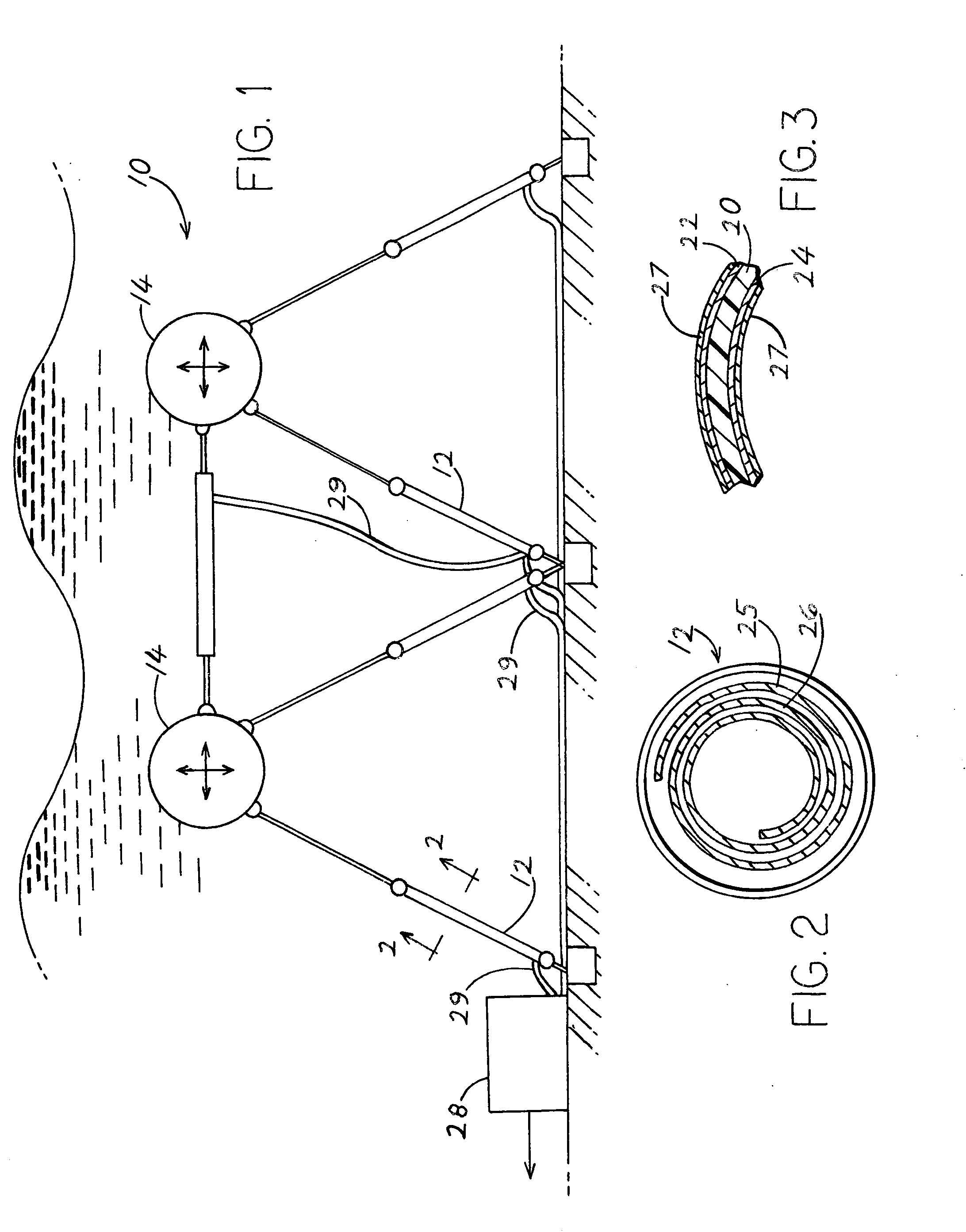
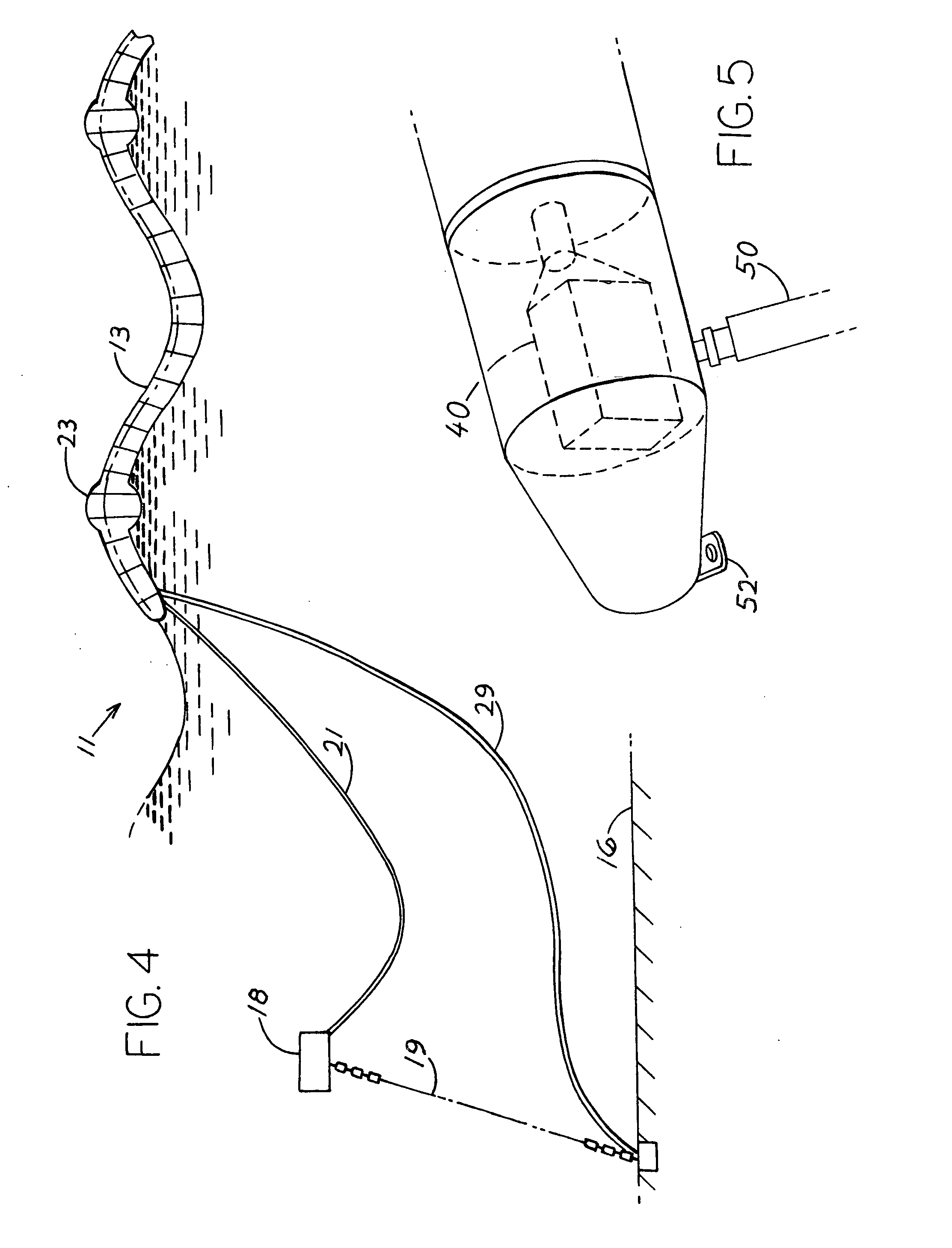
[0027]FIG. 1 shows a first wave energy converting (WEC) system according the invention where electrically interconnected variable capacitor devices 12 are used to generate electricity from sea waves. The capacitor devices are rolls of SM material in a waterproof cover and each has an electrical charge on its electrodes resulting in a voltage between its two electrodes. FIG. 2 is a cross-section of one of the capacitor devices showing that the layers such as 25, 26 each includes a sheet of SM and its electrodes, which are wound into a spiral with overlapping layers 25, 26. FIG. 3 shows that the capacitor device includes a sheet 20 of stretchable dielectric material, a pair of compliant electrodes 22, 24 lying against or adjacent to opposite faces of the dielectric sheet 20, and water proof sheets 27 that cover the electrodes. In a system that applicant has designed, there are thirty-eight layers, each having SM material of the EAP (electro active polymer) type of 84 μm (0.084 mm) thi...


PUM


Abstract

An electricity generator having variable capacitors that each includes a repeatedly stretched and relaxed sheet (20, FIG. 3) of SM (stretchable material) and electrodes (22, 24) lying against opposite faces of the sheet, which includes a power extraction unit (110, FIG. 9) coupled to the electrodes of at least a pair of capacitors that are activated out of phase with each other. The unit directs an electrical charge (current) from a first pair of electrodes that have a higher voltage, to one or more second pairs of electrodes that have a lower voltage, to recharge the second pairs of electrodes. During the current flow electrical power is extracted by the drop in voltage of current passing through the unit. The power extraction unit can be provided with a control unit that has voltage detectors (54) and that selectively connect capacitors, based on their voltages, for maximum efficiency in generating power output.

Description

CROSS-REFERENCE[0001]Applicant claims priority from U.S. provisional patent application Ser. No. 61 / 224,329 filed Jul. 9, 2009 and priority from U.S. provisional patent application Ser. No. 61 / 187,597 filed Jun. 16, 2009.BACKGROUND OF THE INVENTION[0002]Energy conversion systems are known that can obtain power from varying environmental conditions such as from sea waves by using the waves to move parts repeatedly back and forth.[0003]Applicant's patent U.S. Pat. No. 7,632,041 discloses a system for generating electrical power from waves, where an electricity-generating stretchable material (SM) is coupled to a static part and to a displaceable part that move with the waves. The SM material functions like a variable capacitor. As a part of the system is moved back and forth, it can be made to repeatedly stretch and relax a quantity (e.g. a sheet) of SM which is preferably EAP (electro active polymer) material. A pair of electrodes lies against the opposite surfaces of a sheet of SM m...

Claims


Application Information

Patent Timeline
IPC IPC(8): F03B13/18H02N1/08
CPCF03B13/185F03B13/1855F03B13/20F05B2220/706F05B2220/7066F05B2240/917H02N1/08Y02E10/38Y02E10/30
Inventor JEAN, PHILIPPE F.FOURMON, ARNAUD
Owner SINGLE BUOY MOORINGS INC
Learn More