
Miniature Motor

a miniature motor and motor body technology, applied in the field of miniature motors, can solve the problems of limited reduction of the overall axial height of the motor, limitation of the miniaturization design limitation of the reduction of the overall axial height of the heat-dissipating fan, so as to achieve simplified structure of the miniature motor and reduce the axial height of the miniature motor

Inactive Publication Date: 2010-12-16
SUNONWEALTH ELECTRIC MACHINE IND
View PDF5 Cites 22 Cited by
  • Summary
  • Abstract
  • Description
  • Claims
  • Application Information

AI Technical Summary

Benefits of technology

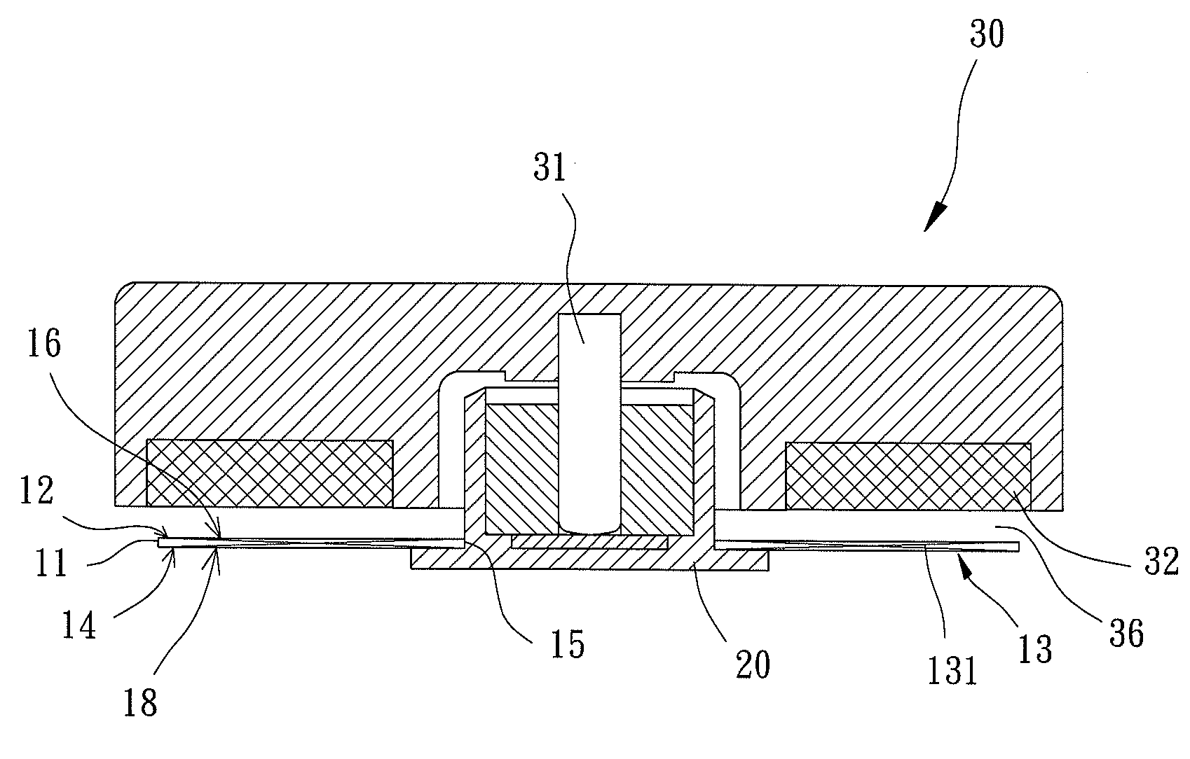
[0008]The present invention solves this need and other problems in the field of miniaturization of motors by providing, in a preferred form, a miniature motor including a base having a layout layer with first and second faces spaced along an axis. The layout layer includes a coil unit. The base further includes an outer layer provided on the first face of the layout layer. A shaft seat is provided on the base. A rotor includes a shaft and a permanent magnet. The shaft is coupled to the shaft seat and rotatable about the axis. The permanent magnet is aligned with the coil unit. An air gap is formed between the permanent magnet and the outer layer of the base. The coil unit is integrated into the base such that the coil unit is outside of the air gap. The axial height of the miniature motor is reduced, and the structure of the miniature motor is simplified.
[0011]In a preferred form, the base includes a through-hole extending along the axis, and the shaft seat is received in the through-hole, allowing easy assembly. In another preferred form, the shaft seat is integrally formed with the base as a single continuous monolithic piece to simplify the structure.

Problems solved by technology

The coil is mounted on and protrudes from a surface of the circuit board, leading to limitation of reduction in the overall axial height of the motor.
When the motor is utilized in a heat-dissipating fan or the like, miniaturization design of the heat-dissipating fan is limited.
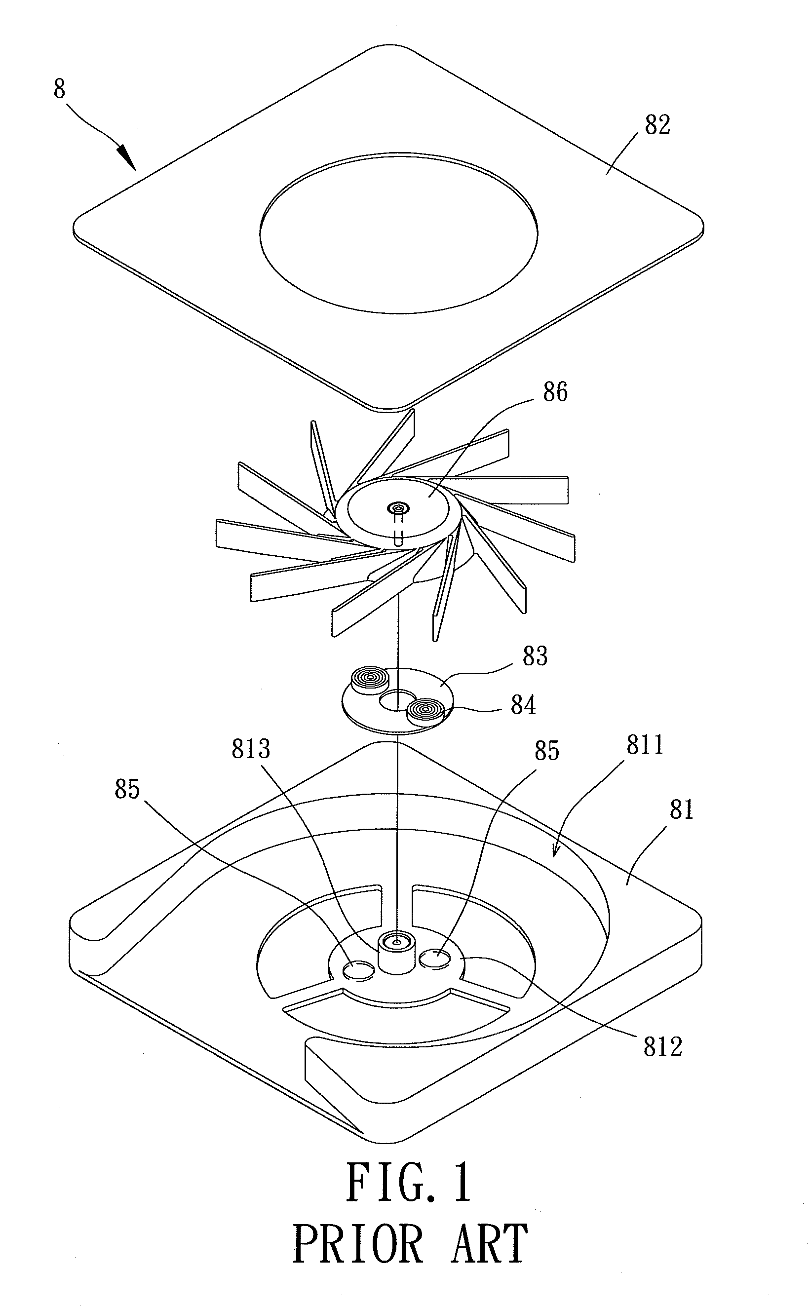
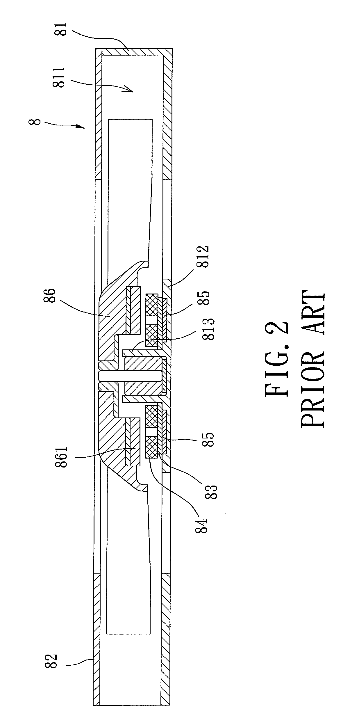
However, the axial heights of the circuit board 83 and the coil unit 84 outside of the circuit board 83 cause limitation to the reduction in the overall axial height of the heat-dissipating fan.
As a result, it is difficult to achieve light, compact design of the heat-dissipating fan 8 and, thus, difficult to mount the heat-dissipating fan 8 in miniature electronic devices or equipment.
However, the axial heights of the base 91 and the coil unit 912 cause limitation to the reduction in the overall axial height of the heat-dissipating fan 9.
As a result, it is difficult to achieve light, compact design of the heat-dissipating fan 9 and, thus, difficult to mount the heat-dissipating fan 9 in miniature electronic devices or equipment.

Method used


Image

  • Miniature Motor
  • Miniature Motor
  • Miniature Motor

Examples


Embodiment Construction

[0024]A miniature motor of a first embodiment according to the preferred teachings of the present invention is shown in FIGS. 5 and 6. The miniature motor includes a base 10, a shaft seat 20, and a rotor 30. The base 10 includes a layout layer 11 and an outer layer 12. The base 10 is preferably a printed circuit board and has opposite first and second faces 16 and 18 spaced along an axis. The layout layer 11 includes coil unit 13 that can be formed by integral formation. As an example, the coil unit 13 can be formed in the layout layer 11 by layout. The coil unit 13 includes a plurality of electrically connected coils 131. The outer layer 12 is electrically insulative and is provided on the first face 16 of the base 10 to form an electrically insulating layer for the layout layer 11. An electrically insulating bottom layer 14 is provided on the second face 18 of the base 10 to form an electrically insulating layer for the layout layer 11. The layout layer 11 is intermediate the oute...


PUM


Abstract

A miniature motor includes a base having a layout layer with two faces spaced along an axis. The layout layer includes a coil unit. The base further includes an outer layer provided on one of the faces of the layout layer. A shaft seat is provided on the base. A rotor includes a shaft and a permanent magnet. The shaft is coupled to the shaft seat and rotatable about the axis. The permanent magnet is aligned with the coil unit. An air gap is formed between the permanent magnet and the outer layer of the base. The coil unit is integrated into the base such that the coil unit is outside of the air gap. The axial height of the miniature motor is reduced, and the structure of the miniature motor is simplified.

Description

BACKGROUND OF THE INVENTION[0001]1. Field of the Invention[0002]The present invention relates to a miniature motor and, more particularly, to a miniature motor with a reduced axial height and with a reduced volume.[0003]2. Description of the Related Art[0004]Currently available motors generally include a stator and a rotor. The stator includes a coil, a circuit board, and other components. The coil is mounted on and protrudes from a surface of the circuit board, leading to limitation of reduction in the overall axial height of the motor. When the motor is utilized in a heat-dissipating fan or the like, miniaturization design of the heat-dissipating fan is limited.[0005]FIGS. 1 and 2 show a conventional heat-dissipating fan 8 including a housing 81 and a lid 82 mounted on top of the housing 81. The housing 81 includes a compartment 811 in which a base 812 is formed. A circuit board 83 and a coil unit 84 are mounted on the base 812. The base 812 further includes at least two positioni...

Claims


Application Information

Patent Timeline
IPC IPC(8): H02K5/00H02K21/12H02K11/00
CPCH02K1/182H02K3/26H02K5/1675H02K21/24H02K11/215H02K11/33
Inventor HORNG, ALEXYIN, TSO-KUOCHENG, TSUNG-HSIN
Owner SUNONWEALTH ELECTRIC MACHINE IND
Learn More