Modular Apparatus for Magnetic Resonance Imaging

a module and magnetic resonance imaging technology, applied in the field of magnetic resonance imaging, can solve the problems of affecting the image quality of the imaging center, the cost of rescheduling, so as to reduce the coupling between the overlapping antennae

Active Publication Date: 2010-12-16
NEOCOIL
View PDF19 Cites 52 Cited by
  • Summary
  • Abstract
  • Description
  • Claims
  • Application Information

AI Technical Summary

Benefits of technology

[0015]Thus, it is a feature of this invention to provide a modular system for detecting the NMR signals generated during magnetic resonance imaging. The separate antenna arrays allow freedom of placement, such as anterior and posterior positioning of an area to be imaged, to achieve desired coverage of an anatomical region.
[0016]As still another aspect of this invention, the antenna array is generally rectangular and may be selectively positioned in a generally planar first state or a generally arcuate second state. A spacer block extending between a first edge and a second edge of the antenna array at a first end of the antenna array is included. The spacer block is configured to be on the outer surface of the antenna array when the antenna array is in the second state and is configured to engage the inner surface of a second end of the antenna array overlapping the first end of the antenna array such that the second end of the antenna array is positioned at an angle to the first end of sufficient magnitude to minimize coupling between overlapping antennae.

Problems solved by technology

For example, the same housing sized to fit a pediatric torso will not fit the torso of a large adult.
However, requirements for designing the housing for patient comfort and for stabilizing the region of interest are often at odds with the requirements for improving the reception of the antennae within the housing.
However, design considerations for the housing to achieve patient comfort and stability impose practical limitations on how close the antennae may be placed to the anatomical region of interest.
Due to the expense of each housing, an imaging center will often have only one of any particular size or configuration of housing.
As a result, the imaging center loses revenue and must reschedule patients that would otherwise require that housing during the time it is out for repair.

Method used


Image

  • Modular Apparatus for Magnetic Resonance Imaging
  • Modular Apparatus for Magnetic Resonance Imaging
  • Modular Apparatus for Magnetic Resonance Imaging

Examples


Embodiment Construction

[0046]The various features and advantageous details of the subject matter disclosed herein are explained more fully with reference to the non-limiting embodiments described in detail in the following description.

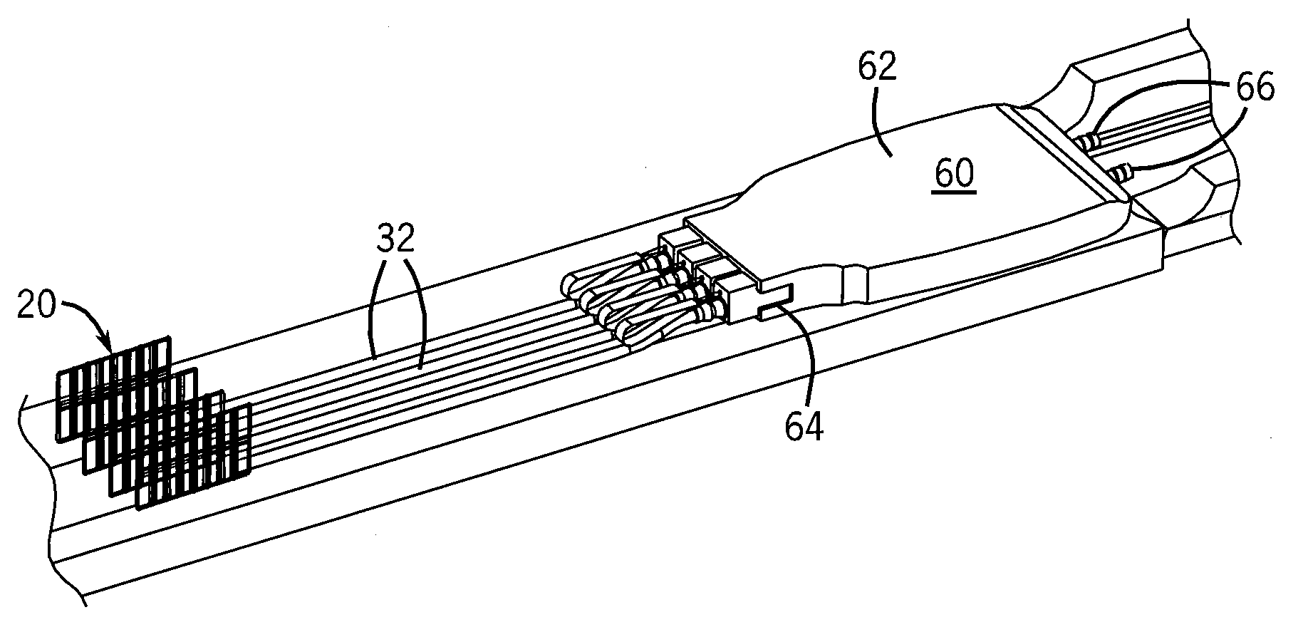
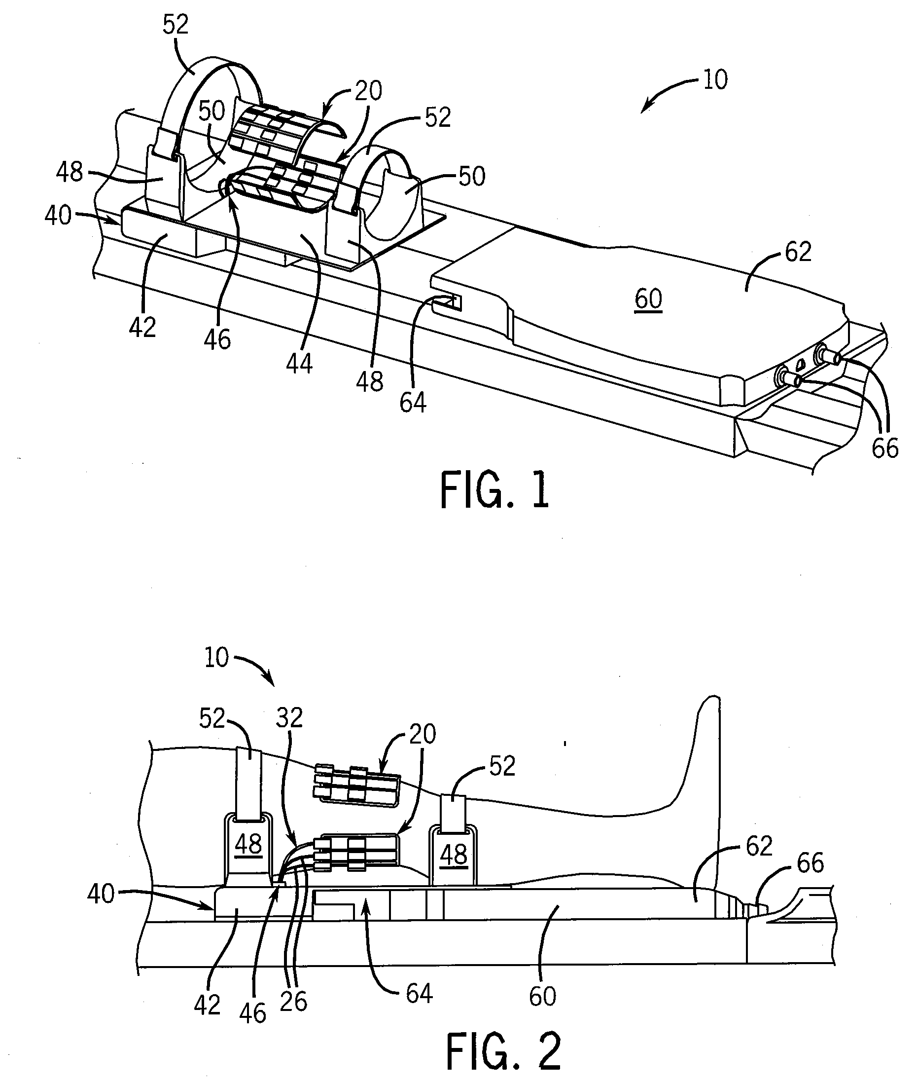
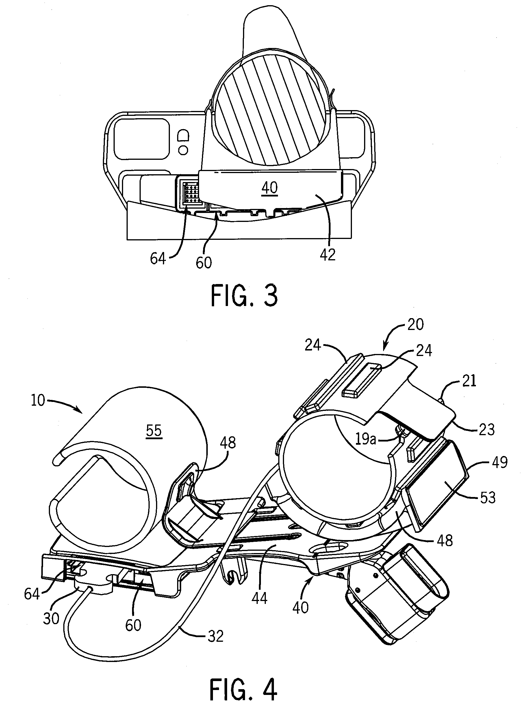
[0047]Referring to FIGS. 1-3, a first embodiment of an MM imaging receiver 10 according to the present invention is illustrated. In this embodiment, the imaging receiver 10 is configured to obtain images of a patient's leg and, specifically, the knee. The imaging receiver 10 preferably includes three fundamental components: the antenna arrays 20, the patient stabilization structure 40, and the preamplifier module 60. Each antenna array 20 is a modular structure including multiple antenna loops 22. The antenna arrays 20 preferably include eight, sixteen, or twenty-four individual antenna loops 22 arranged in one or more rows. Each row, for example, may contain eight antenna loops 22. The antenna loops 22 are further arranged such that adjacent loops 22 overlap to reduce mutua...


PUM


Abstract

The present invention discloses a modular MRI imaging system. The imaging system includes MRI radio-frequency antenna arrays separate from the patient support structure. The antenna arrays are affixed to a thin, flexible film such that they may be located next to the anatomical region of interest. In addition, multiple antenna arrays may be configured in various planar or three-dimensional arrangements to optimize the FOV and SNR. Separate patient support structures are provided that enhance ergonomics and patient stabilization. By removing the antenna from the housing, the support structures may be designed without the constraints of supporting the antenna or the associated electronics. The MRI imaging system further employs a preamplifier module. The preamplifier module houses the preamplifier and much of the other associated circuitry for each of the antennae. The preamplifier module operates to combine the signals from the antenna arrays and pass the signals to the MRI system.

Description

CROSS-REFERENCE TO RELATED APPLICATIONS[0001]This application claims priority to U.S. provisional application Ser. No. 61 / 187,522, filed Jun. 16, 2009, the entire contents of which is incorporated herein by reference.BACKGROUND OF THE INVENTION[0002]The subject matter disclosed herein relates to magnetic resonance imaging. More specifically, the subject matter relates to a modular and separable architecture of the radio frequency antenna arrays, the amplifier and channel combination circuitry, and the patient support, or stabilization, devices.[0003]As is known to those skilled in the art, a magnetic resonance image (MRI) detects the faint nuclear magnetic resonance (NMR) signals given off by protons in the presence of a strong magnetic field after excitation by a radio frequency signal. The NMR signals are detected using antennae, commonly referred to as “coils.”[0004]Antennae are configured to send signals to the host MRI scanner that enable trained practitioners to make appropria...

Claims


Application Information

Patent Timeline
Patent Type & Authority Applications(United States)
IPC IPC(8): G01R33/48
CPCA61B5/0555G01R33/34007G01R33/34084G01R33/3415G01R33/3621A61B5/055
Inventor BROWN, BRIANWOLFF, STEVENJOHNSON, KYLEWELLS, GLENN
Owner NEOCOIL
Why Eureka
Try Eureka