Class D Power Amplifier

a power amplifier and amplifier technology, applied in the direction of amplifiers, dc amplifiers with modulator-demodulator, semiconductor devices/discharge tubes, etc., can solve the problems of high probability of correlation (continuity) changes in pulse width, unsatisfactory abnormal sound such as so-called popping noise, etc., to prevent the generation and eliminate 100%.

Inactive Publication Date: 2010-12-16
ROHM CO LTD
View PDF10 Cites 25 Cited by
  • Summary
  • Abstract
  • Description
  • Claims
  • Application Information

AI Technical Summary

Benefits of technology

[0065]A class D power amplifier of the present invention is capable of preventing generation of abnormal sound which is likely to occur upon abrupt signal switching, because a signal switching circuit therein is switched slowly for mute-on / off within a predetermined period of time. A PWM circuit therein provides pulse width modulation to an analog signal to obtain a binarized signal. Thereafter, in the case where the duty ratio thereof is around 0%, a duty ratio adjusting circuit adjusts the duty ratio to be higher than that. On the other hand, in the case where the duty ratio is around 100%, the duty ratio adjusting circuit adjusts the duty ratio to be lower than that. Accordingly, popping noise occurring when the duty ratio is around 0% and 100% can be eliminated.

Problems solved by technology

In general audio amplifying circuits as well as these class D power amplifiers, unpleasant abnormal sound such as so-called popping noise may be generated upon power-on or power-off.
Transient voltage ΔSRL causes current to flow in speaker RL, resulting in generation of popping noise.
In other words, Patent Document 6 indicates that in the mute-off state, the pulse width of the PWM signal is changed with a certain level of correlation (continuity) in accordance with the waveform of the audio signal, whereas when the PWM signal is suddenly changed in waveform to have a duty ratio of 50% upon entering the mute-on state, the pulse width thereof is abruptly and significantly changed, with the result that the correlation (continuity) of changes in pulse width is highly likely to be lost.

Method used


Image

  • Class D Power Amplifier
  • Class D Power Amplifier
  • Class D Power Amplifier

Examples


first embodiment

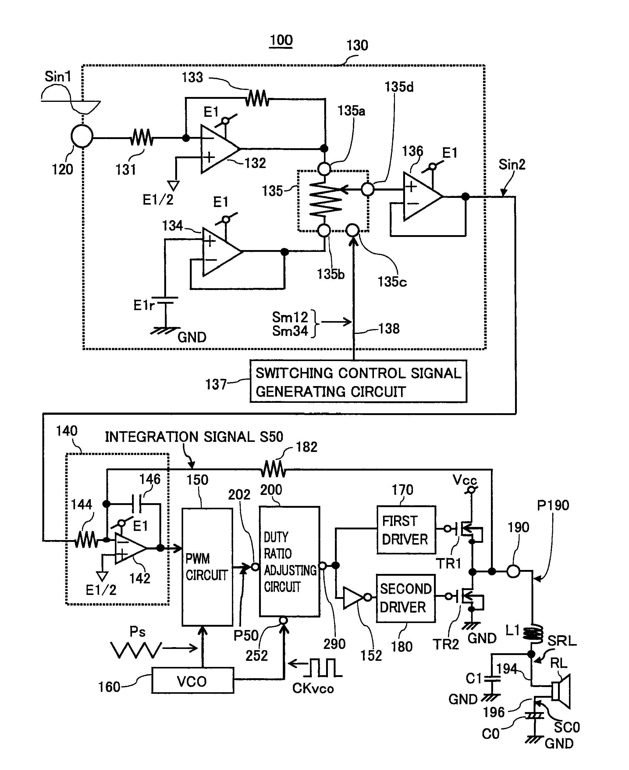
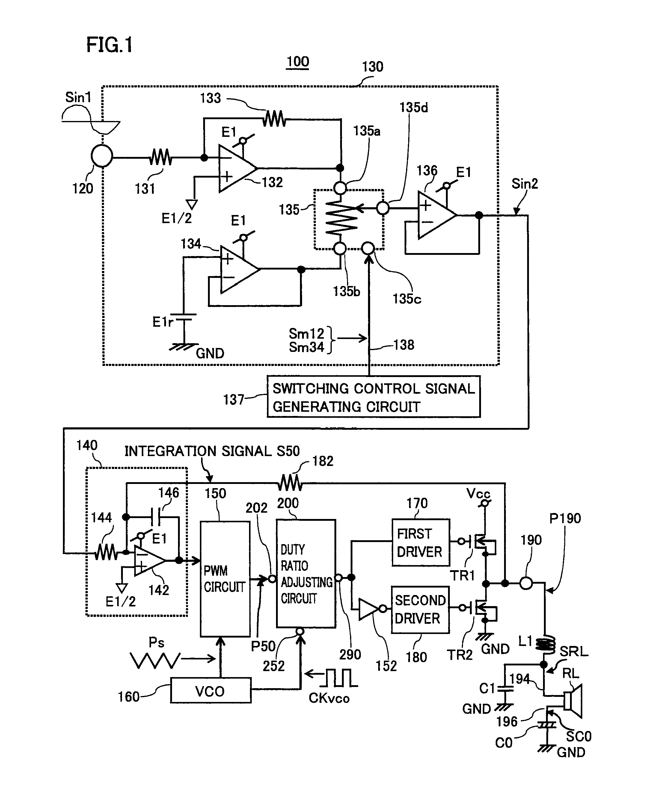
[0084]FIG. 1 shows a circuit block diagram of a class D power amplifier according to a first embodiment of the present invention. Specifically, FIG. 1 shows a class D power amplifier of single-ended type in which one signal output terminal is connected to one speaker. Class D power amplifier 100 has a signal input terminal 120 for receiving an analog input signal Sin1, an analog signal processing unit 130 for processing the analog signal, an integrating circuit 140, a PWM circuit 150, a VCO 160, a duty ratio adjusting circuit 200, a first driver 170, a second driver 180, power transistors TR1, TR2, and a signal output terminal 190. Signal output terminal 190 is connected to an inductor L1, a capacitor C1, a coupling capacitor C0, and a speaker RL. Inductor L1 and capacitor C1 constitute a low pass filter, and coupling capacitor C0 is provided to cut off a direct-current component. The order of inductance of inductor L1 is selected to be several ten μH, the capacitance value of capac...

second embodiment

[0207]FIG. 11 is a circuit block diagram showing a configuration of a class D power amplifier 101 according to a second embodiment of the invention of the present application, in comparison to FIG. 1. FIG. 12(a)-FIG. 12(d) are signal waveform diagrams showing operations of class D power amplifier 101. Referring to FIG. 11, class D power amplifier 101 is different from class D power amplifier 100 of FIG. 1 in that an analog signal processing unit 102 replaces analog signal processing unit 130, current sources 103, 104, and a capacitor 105 are additionally provided, and a duty ratio adjusting circuit 106 replaces duty ratio adjusting circuit 200.

[0208]Analog signal processing unit 102 is obtained by removing amplifier 134 from analog signal processing unit 130. Signal switching circuit 135 has a second terminal 135b to which a direct current voltage E1 / 2, which is the half of power source voltage E1, is applied. Signal switching circuit 135 is constituted by, for example, a variable v...


PUM


Abstract

A class D power amplifier includes: a signal input terminal for receiving an analog signal; an analog signal processing unit for amplifying the analog signal; an integrating circuit for integrating the analog signal received from analog signal processing unit; a PWM circuit for providing pulse width modulation to an integration signal received from the integrating circuit, and outputting a resulting pulse width modulation signal having a duty ratio falling within a first duty ratio range; a duty ratio adjusting circuit for adjusting the pulse width modulation signal, received from the PWM circuit, to have a pulse width falling within a second duty ratio range narrower than the first duty ratio range; a first driver and a second driver each for processing the pulse width modulation signal received from the duty ratio adjusting circuit; and power transistors.

Description

TECHNICAL FIELD[0001]The present invention relates to a class D power amplifier, in particular, a class D power amplifier having a circuit function of reducing and eliminating generation of popping noise.BACKGROUND ART[0002]In response to demands for reduced number of components and use of a single power source for audio amplifying circuits in TVs, personal computers, AV receivers, car audio equipment, and the like, class D power amplifiers of single-ended type are used. In general audio amplifying circuits as well as these class D power amplifiers, unpleasant abnormal sound such as so-called popping noise may be generated upon power-on or power-off. To avoid such a problem, various countermeasures have been taken.[0003]FIG. 13 schematically shows a conventional class D power amplifier of single-ended type. Class D power amplifier 300 has an integrated circuit portion 310. Integrated circuit portion 310 is literally interpreted as a portion in which respective electronic elements ar...

Claims


Application Information

Patent Timeline
Patent Type & Authority Applications(United States)
IPC IPC(8): H03F1/00H03F3/217
CPCH03F3/217
Inventor TAKAGI, RYOTAKAHATA, KOJI
Owner ROHM CO LTD
Why Eureka
Try Eureka