Separator separating chips and other material from coolant and method

Inactive Publication Date: 2010-12-23
MAHAS BRIAN +3
View PDF30 Cites 2 Cited by
  • Summary
  • Abstract
  • Description
  • Claims
  • Application Information

AI Technical Summary

Benefits of technology

[0006]The separator of this invention may be integrated into a work station to separate chips in a coolant generated by the work station from other objects, such as tools, screwdrivers, drill bits, gloves and the like that may be disposed in the coolant. The separator includes a conveyor beneath the work station including an inclined portion removing and conveying the chips and other objects from the coolant received from the work station. The separator further includes a separator plate beneath the conveyor including an inclined portion may extend generally parallel to the inclined porti

Problems solved by technology

Such foreign objects may cause damage to the pump impellers, thereby terminating the entire machining operation until the pumps are cleaned or replaced based upon the degree of damage or

Method used


Image

  • Separator separating chips and other material from coolant and method
  • Separator separating chips and other material from coolant and method
  • Separator separating chips and other material from coolant and method

Examples


Example

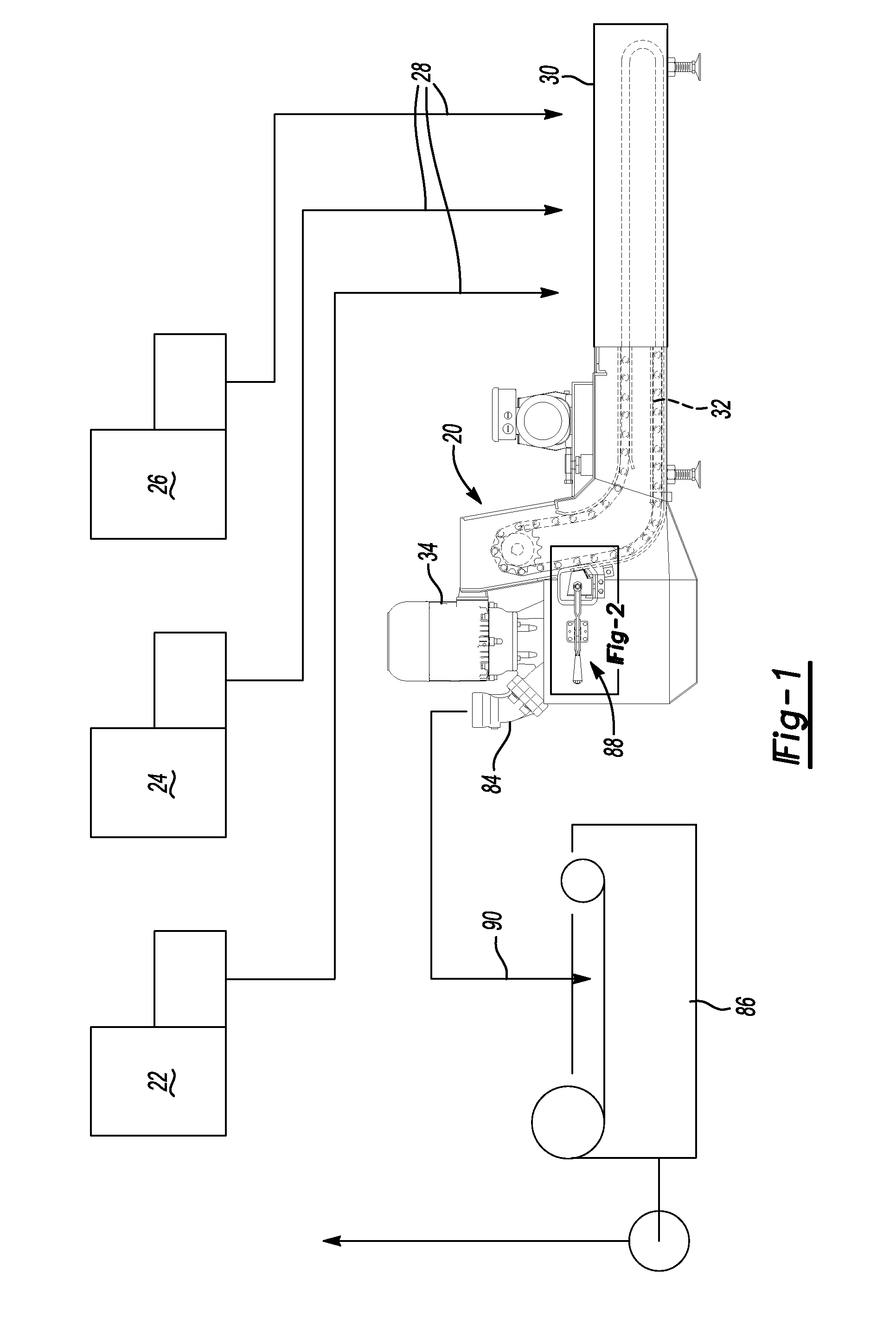
[0019]As set forth above, the separator 20 may be used to separate chips in a coolant generated by the workstation from other objects, such as tools, work gloves or the like. As shown in FIG. 1, the separator 20 may be integrated into workstations 22, 24 and 26 including cutting machines (not shown), wherein chips are generated from the workpiece and coolant, such as cutting oil, is used to cool the cutting tool and the workpiece and the chips generated by the workstations with the cutting oil is then delivered to the separator 20 as shown by arrows 28. As will be understood by those skilled in this art, the workstations may be located above an end of the housing 30 and openings may be provided through the housing, wherein the workstations 22, 24 and 26 discharge chips and coolant directly through the opening onto the conveyor 32 described below. As also set forth above, other objects, including tools, drill bits, gloves and the like are often disposed into the coolant which should ...


PUM

PropertyMeasurementUnit
Widthaaaaaaaaaa

Abstract

A separator for separating chips in a coolant generated by a workstation from other objects, including a conveyor having an inclined portion removing chips and other objects from the coolant, a separator plate beneath the conveyor including an inclined portion extending parallel to the conveyor having a plurality of generally parallel slots receiving the chips therethrough and enlarged openings adapted to receive the other objects therethrough, and a pump transferring the chips and coolant to a filter.

Description

RELATED APPLICATION[0001]This application claims priority to U.S. Provisional Patent Application Ser. No. 61 / 218,629 filed Jun. 19, 2009.FIELD OF THE INVENTION[0002]This invention relates to a separator for separating chips in a coolant generated by a machining work station from other material and a method of separation.BACKGROUND OF THE INVENTION[0003]Modern machining operations typically use a coolant and lubricant, such as cutting oil, and generate chips which are collected in the coolant. The coolant is recycled and re-used in further machining operations and the chips may be a valuable resource which may be collected and recycled. Some machining operations include a lathe tool that that generates circular chip sections by rotating the workpiece, so that the cutting tool can peel off material, creating a smooth round surface. A drill punch is used to remove metal and form a hole or opening. Other tools and machining operations are used for various types of metal removal such as,...

Claims


Application Information

Patent Timeline
IPC IPC(8): F01M11/03B01D35/02
CPCB23Q11/0057Y02P70/10
Inventor MAHAS, BRIANBENSCHOTER, BARRYGELINAS, MARCHUGHES, CHARLES
Owner MAHAS BRIAN
Why Eureka
Try Eureka