Light-emitting diode apparatus

a technology of light-emitting diodes and led elements, which is applied in the direction of lighting and heating apparatus, semiconductor devices for light sources, circuit electrostatic discharge protection, etc., can solve the problems of difficult optical design, difficult to increase the density of mounting led elements, and limitation to acquire a light-source device having high lumen density

Active Publication Date: 2010-12-23
CITIZEN ELECTRONICS CO LTD +1
View PDF3 Cites 136 Cited by
  • Summary
  • Abstract
  • Description
  • Claims
  • Application Information

AI Technical Summary

Benefits of technology

[0020]In mounting a plurality of LED elements, a plurality of units in each of which a plurality of LED elements are serially connected are connected parallel with respect to each other to th

Problems solved by technology

However, in the aforementioned conventional LED light-source unit, because the LED elements are arranged in line, and a light-emitting area has an elongate rectangular shape, there is a problem that an optical design is difficult for the fact that light emitted from the LED elements must

Method used


Image

  • Light-emitting diode apparatus
  • Light-emitting diode apparatus
  • Light-emitting diode apparatus

Examples


first embodiment

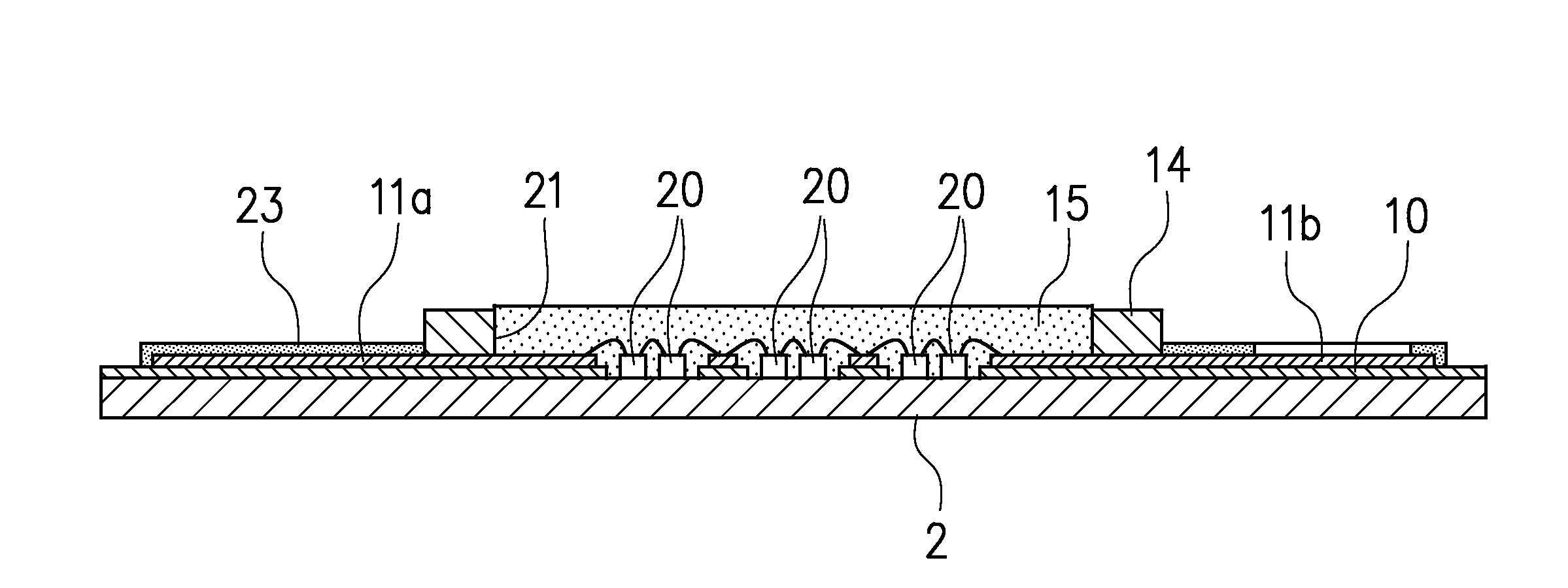
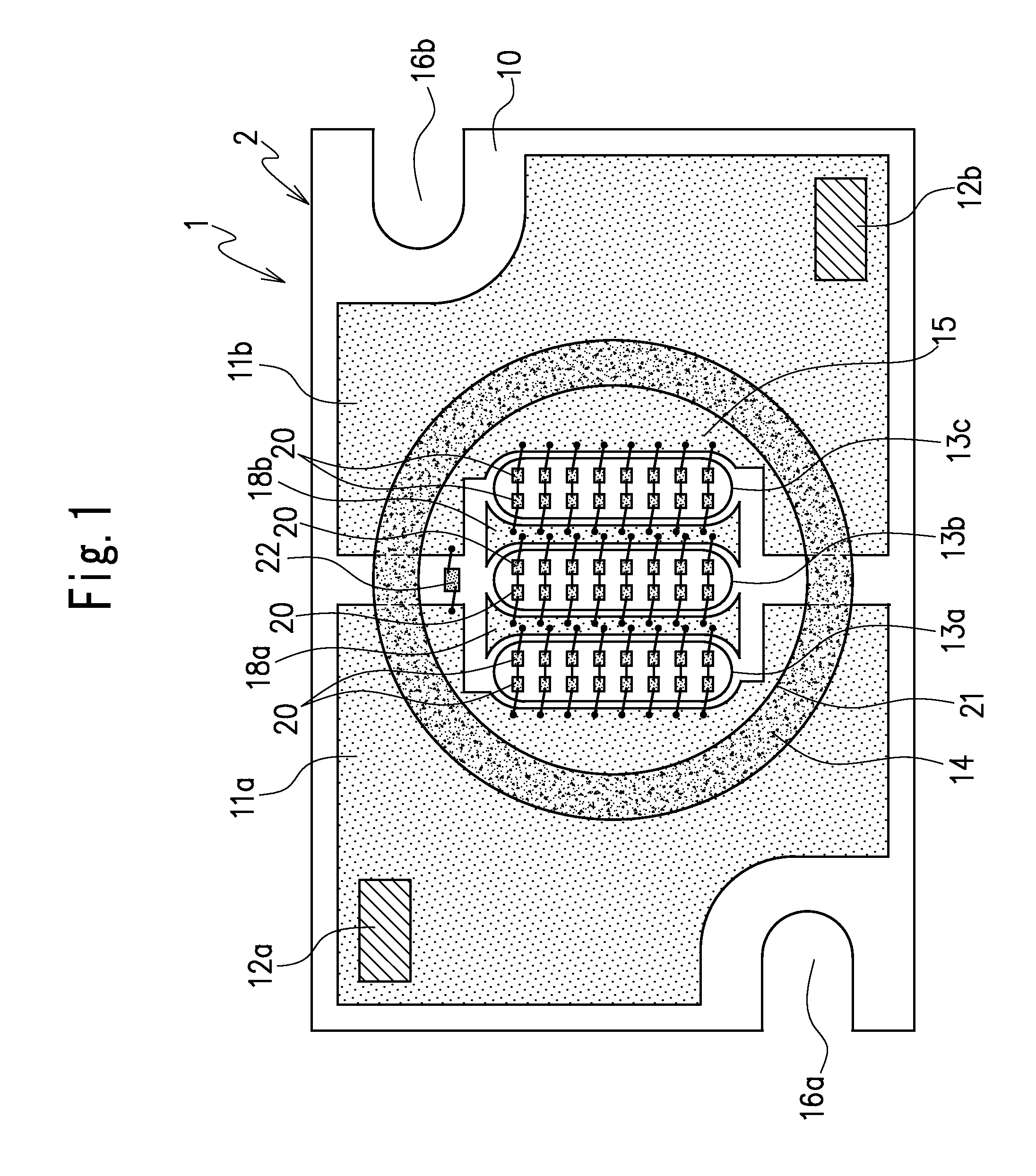
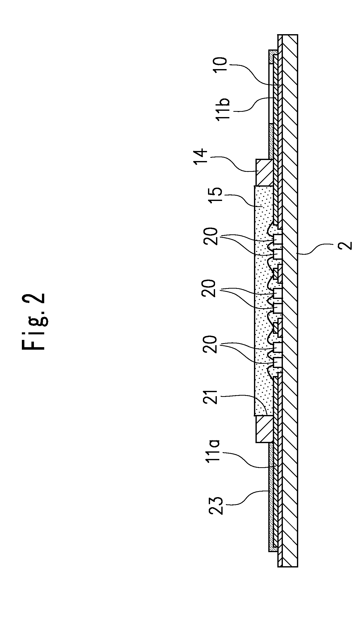
[0040]FIGS. 1 to 6 illustrate an LED apparatus according to a first embodiment of the present invention.

[0041]The LED apparatus 1 in the first embodiment has a structure configured to set a light-emitting area, provide a base-mounting area inside the light-emitting area and mount a plurality of LED elements on the base-mounting area.

[0042]More specifically, the LED apparatus 1 includes a base 2 having thermal conductivity and including, for example, an upper surface, a lower surface opposite the upper surface, and a peripheral edge side surface provided between the upper surface and the lower surface, a thin-plate-shape insulative substrate 10 including an upper surface provided with electrodes 11a, 11b, 18a, and 18b, a lower surface opposite the upper surface, and a plurality of pass-through holes 13a, 13b, and 13c, the lower surface of the substrate 10 being fixed to the upper surface of the base 2, and a frame 14 provided on the substrate 10 (see FIGS. 1 and 2). The base 2 is mad...

second embodiment

[0089]Next, a schematic structure of an LED apparatus according to a second embodiment of the present invention is described with reference to FIG. 7. In this embodiment, in the plurality of light-emitting diode elements, at least two light-emitting diode elements that are extended in a line between the electrodes that are provided along opposite sides of the pass-through hole, and electrically connected in series as a unit of light-emitting diode elements in series. A plurality of the units of light-emitting diode elements in series are arranged parallel with each other in a direction perpendicular to the line of the at least two light-emitting diode elements as the unit, and the units are disposed parallel and electrically connected to the electrodes in parallel.

[0090]The LED apparatus 30 in the second embodiment has a structure in which a large number of LED elements are mounted in a base-mounting area having approximately a square shape which has good mounting efficiency. Becaus...

third embodiment

[0116]Next, an outline of an LED apparatus according to a third embodiment of the present invention is described with reference to FIG. 10.

[0117]The LED apparatus 40 in the third embodiment includes a circular base-mounting area 46 and a plurality of LED elements 41 mounted in the base-mounting area 46. For example, some of these LED elements 41 are dummy elements 42. Because a basic structure of the LED apparatus 40 in the third embodiment is the same as that of the aforementioned first and second embodiments, identical reference numbers are attached to the similar parts, the duplicative description is partially omitted.

[0118]More specifically, the LED apparatus 40 includes a base 2 made of an aluminum material or the like and an insulative substrate 10 fixed to a surface of the base 2 and formed by a thin glass epoxy plated material or the like. The substrate 10 includes three electrodes 32a, 32b and 32c formed by a copper foil covering a large part of the surface of the substrate...


PUM


Abstract

An LED apparatus includes a base having thermal conductivity, an insulative substrate provided on one surface of the base and including electrodes provided on a surface of the substrate, at least one base-mounting area that is an exposed part of the base, exposed within a pass-through hole provided in the substrate, a plurality of LED elements mounted on the base in the base-mounting area and some of the LED elements in a unit electrically connected to the electrodes in series, a plurality of the units are electrically connected in parallel, and a frame disposed to surround the base-mounting area and configured to form a light-emitting area.

Description

CROSS-REFERENCE TO THE RELATED APPLICATION[0001]This application is based on and claims the priority benefit of Japanese Patent Application No. 2009-148996, filed on Jun. 23, 2009, the disclosure of which is incorporated herein by reference in its entirety.BACKGROUND OF THE INVENTION[0002]1. Field of the Invention[0003]The present invention relates to an LED (light-emitting diode) apparatus formed by collecting a plurality of LED elements to be capable of using as various illumination light sources.[0004]2. Description of the Related Art[0005]Conventional LED elements which are compound semiconductors have widely been utilized as light source devices, using characteristics of a long service life and miniaturization. Manufacturing light source devices to emit light of white color or pseudo white color has been promoted with development of blue-LED elements formed by gallium nitride-system-compound semiconductors and so on. In addition, light source devices having high output and high...

Claims


Application Information

Patent Timeline
IPC IPC(8): H01L33/08
CPCF21K9/00H01L25/0753H01L33/62H05K1/021F21V29/76H05K2201/10106H01L2224/48137H05K1/0259H01L2224/48091H01L2924/00014F21V29/763H01L25/167
Inventor KADOTANI, NORIKAZUFUKASAWA, KOICHIIMAI, SADATO
Owner CITIZEN ELECTRONICS CO LTD
Why Eureka
Try Eureka