Method for determining the configuration of an ophthalmic lens, ophthalmic lens produced according to said method, and method for producing said lens

Active Publication Date: 2010-12-23
SAV IOL
View PDF7 Cites 22 Cited by
  • Summary
  • Abstract
  • Description
  • Claims
  • Application Information

AI Technical Summary

Benefits of technology

[0028]The present invention intends to avoid drawbacks for the ophthalmic lens of the prior art by offering lenses with an extended

Problems solved by technology

Moreover, the extension of this depth of focus is not performed in detriment of th

Method used


Image

  • Method for determining the configuration of an ophthalmic lens, ophthalmic lens produced according to said method, and method for producing said lens
  • Method for determining the configuration of an ophthalmic lens, ophthalmic lens produced according to said method, and method for producing said lens
  • Method for determining the configuration of an ophthalmic lens, ophthalmic lens produced according to said method, and method for producing said lens

Examples


Embodiment Construction

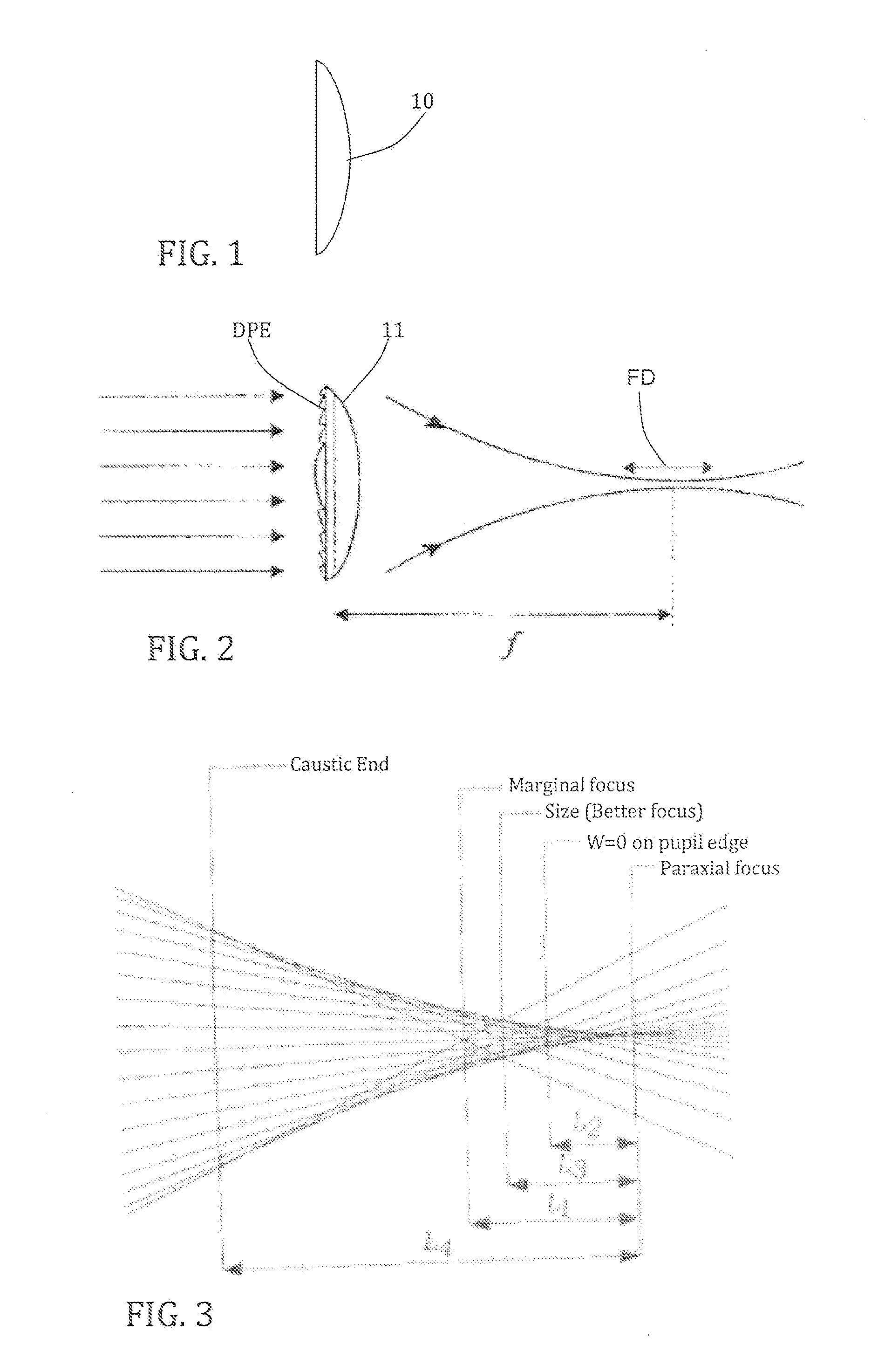
[0068]A particular embodiment of the invention is described with reference to the attached figures. This example is based on an intraocular ophthalmic lens IOL (Intraocular lens). It should be noted however that the methods of the invention are also applied to all types of ophthalmic lens such as those mentioned above.

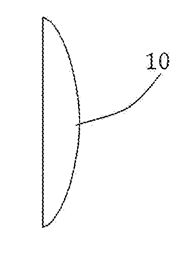
[0069]The determination method for the configuration of a lens as described in the present application can be split into three steps. One of these steps comprises the determination of the shape of a base optical corrective element 10 based on parameters such as the desired final power of the ophthalmic lens, the correction or not of the lens aberrations or of the cornea of the user, such as spherical aberrations, chromatic aberrations or high order aberrations, etc. This base optical corrective element can have a flat, convex, concave, aspheric and / or toric surface.

[0070]The resulting lens can have a positive, negative or null power; it can also be multifocal or partic...


PUM


Abstract

The invention relates to a method for determining the configuration of an ophthalmic lens intended to correct the visual acuity of a user, this method comprising the steps of determining the form of a base optical corrective element according to at least one of the following parameters: the desired power of the ophthalmic lens; the desired resolution or modulation transfer function MTF; the desired extent of the correction of the spherical aberrations (SA) of said ophthalmic lens; the desired extent of the correction of the spherical aberrations (SA) of the cornea of the user; the desired extent of the correction of the chromatic aberrations of said ophthalmic lens; the desired extent of the correction of the chromatic aberrations of the cornea of the user; the desired extent of the correction of high order aberrations (HOA). Furthermore the method comprises a step of determining the profile of a diffractive phase element (DPE) structure, said determination comprising the steps of defining a desired depth of focus of said ophthalmic lens; of calculating the phase distribution to be created at the entrance pupil of the lens, from the desired depth of focus; of finding the phases which minimize the differences between the effective phase distribution and the desired phase distribution and of converting the phase data into geometrical data in order to define the profile of the diffractive phase distribution structure. The method finally comprises juxtaposing the resulting diffractive phase element structure and the base optical corrective element.
The invention also concerns a lens obtained according to the above mentioned method as well as a method for the producing such a lens.

Description

TECHNICAL DOMAIN[0001]The present invention relates to a method for determining the configuration of an ophthalmic lens. It also relates to an ophthalmic lens obtained according to this method as well as a method for producing such an ophthalmic lens.[0002]This invention generally refers to ophthalmic lenses with extended depth of focus (E-DOF) and thus correspondent extended depth of field. These hybrid refractive-diffractive lenses use a diffractive phase element (DPE) on one of the surfaces of the lens and an aspheric geometry on the other surface. These lenses allow the selection of the depth of focus, even a very large one, while maintaining an admissible relatively constant resolution on the focus field. The surface carrying the diffractive phase element can be replaced by an aspheric surface with similar optical characteristics. The hybrid lens is then made of two aspheric surfaces. The depth of focus can be created on segments for instance for the near vision and / or for far ...

Claims


Application Information

Patent Timeline
IPC IPC(8): G02C7/02
CPCA61F2/16G02C7/028G02C2202/22G02C7/06G02C2202/20G02C7/042A61F2/1613A61F2240/002A61F2/1637
Inventor APTER, ROBERTAPTER, ALAIN
Owner SAV IOL
Why Eureka
Try Eureka