Optical coherence tomographic imaging apparatus and optical coherence tomographic imaging method

a tomographic imaging and optical coherence technology, applied in the field of optical coherence tomographic imaging apparatus and optical coherence tomographic imaging method, can solve the problems of difficult to project the measuring beam and take a long time to adjust the optical system, and achieve the effect of long tim

Active Publication Date: 2010-12-23
CANON KK
View PDF18 Cites 30 Cited by
  • Summary
  • Abstract
  • Description
  • Claims
  • Application Information

AI Technical Summary

Benefits of technology

[0007]The apparatus disclosed in Patent Art. 1 (Japanese Patent Application Laid-Open No. 2002-174769) can observe a noticeable region in a large structure in a vital sample confirmed with minuter resolution by OCT by changing to OCM, thereby solving a problem that it takes a long time for adjustment for projecting a measuring beam in OCM with a shallow depth of focus at a predetermined position.
[0010]It is an object of the present invention to provide an optical coherence tomographic imaging apparatus and an optical coherence tomographic imaging method, which can shorten the imaging time upon acquiring a tomographic image with high resolution by OCT, in view of the above-described problems.
[0033]According to the present invention, an optical coherence tomographic imaging apparatus and an optical coherence tomographic imaging method which can shorten the imaging time upon acquiring a tomographic image with high resolution by an OCT apparatus can be realized.

Problems solved by technology

However, Patent Art. 1 (Japanese Patent Application Laid-Open No. 2002-174769) does not at all consider a problem caused by making a beam diameter of a measuring beam large using the beam diameter converting optical system upon tomographic imaging with high resolution by imaging by the OCT apparatus.
However, when the beam diameter of the measuring beam is made large in such a manner, the depth of focus becomes shallow, so that it is difficult to project the measuring beam at a predetermined position, and it takes a long time to adjust the optical system.

Method used


Image

  • Optical coherence tomographic imaging apparatus and optical coherence tomographic imaging method
  • Optical coherence tomographic imaging apparatus and optical coherence tomographic imaging method
  • Optical coherence tomographic imaging apparatus and optical coherence tomographic imaging method

Examples


example 1

[0098]An OCT apparatus (or optical coherence tomographic information acquisition apparatus) in Example 1 is described. In this Example, TD-OCT (time domain OCT) for acquiring a tomographic image of a retina in particular is described.

[0099]However, the present invention is not limited to such TD-OCT, and it goes without saying that the present invention may also be applied to FD-OCT (fourier domain OCT).

[0100]First, the schematic construction of the optical system of the OCT apparatus in this Example is described.

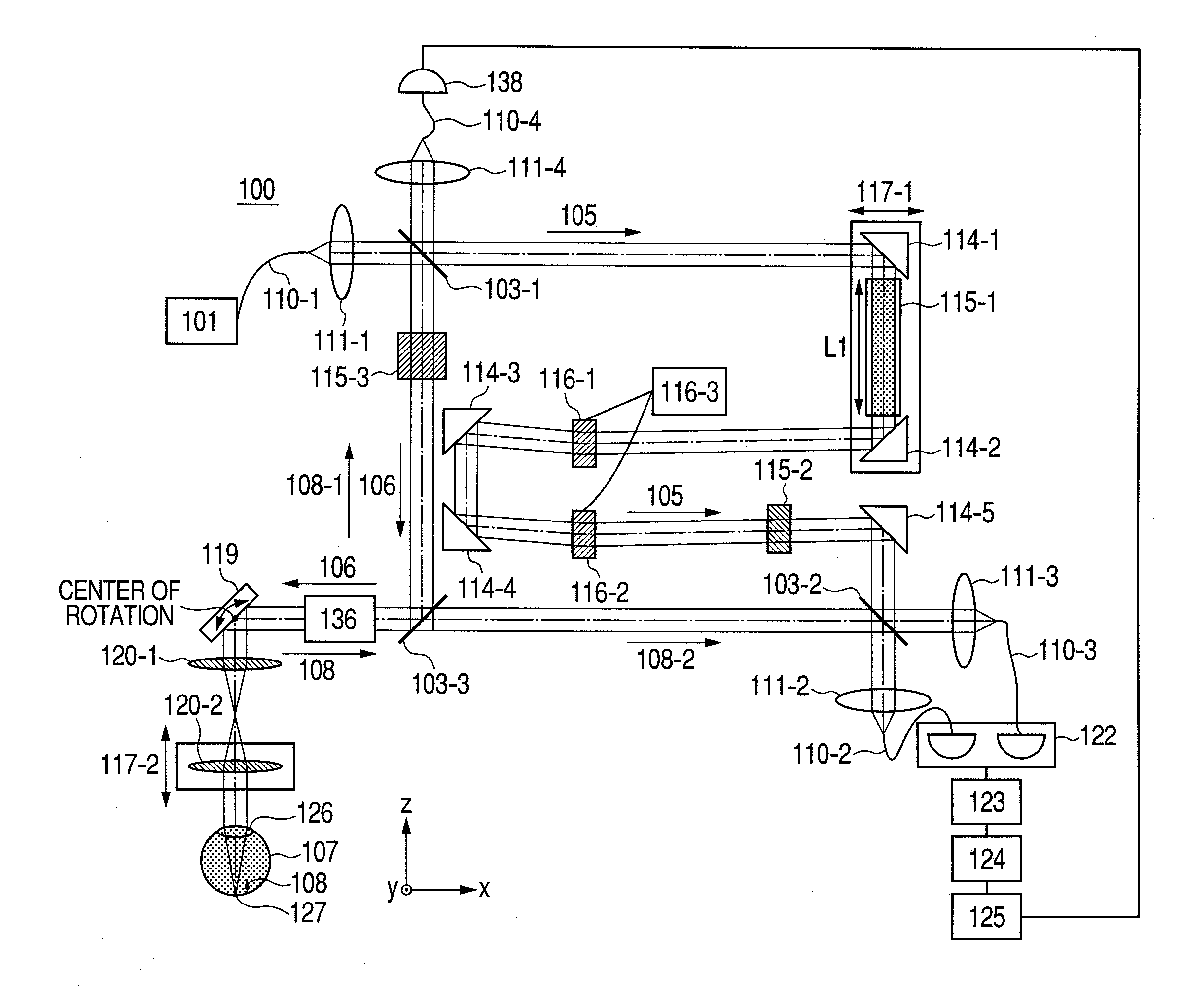
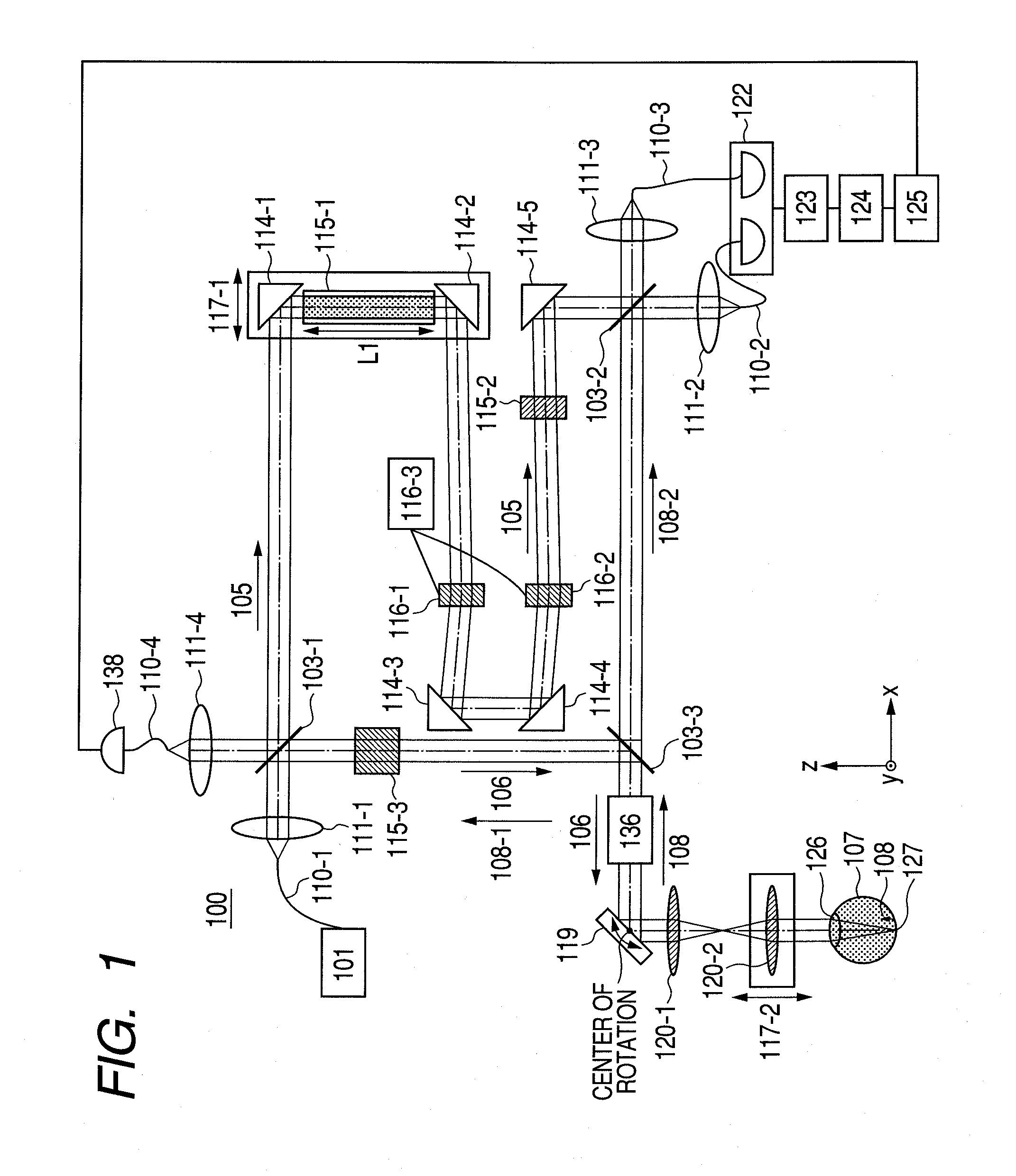
[0101]FIG. 1 illustrates the schematic construction of the whole optical system of the OCT apparatus in this Example. In FIG. 1, an OCT apparatus 100 and an eye (or inspection object) 107 measured by the OCT apparatus 100 are illustrated.

[0102]The OCT apparatus is constructed by the following element: a light source 101, beam splitters 103-1 to 103-3, single mode fibers 110-1 to 110-4, lenses 111-1 to 111-4, and 120-1 and 120-2, mirrors 114-1 to 114-5, dispersion compensati...

example 2

Optical Fiber

[0177]In Example 2, an exemplary construction in which any of the optical paths shown in Example 1 is constructed by an optical fiber is described.

[0178]FIG. 4 illustrates the schematic construction of the whole optical system of an OCT apparatus in this Example. In FIG. 4, the same or corresponding elements to those of Example 1 illustrated in FIG. 1 are given the same reference sign, and so the description of the redundant elements is omitted.

[0179]The OCT apparatus 200 illustrated in FIG. 4 is constructed by single mode fibers 130-1 to 130-10, photocouplers 131-1 to 131-3 and the like.

[0180]In this Example, the OCT apparatus 200 is used as an apparatus for acquiring a tomographic image of the retina 127 of an eye 107 in an eye to be inspected. In this Example, a part of the optical system is constructed by using the optical fibers, thereby miniaturizing the apparatus.

[0181]The apparatus has a fundamental construction that does not differ from that in Example 1 except...

example 3

Beam Diameter Adjustment Based on Pupil Diameter

[0214]In this Example, after the adjusting method before acquiring the tomographic image in Example 1 or 2 in the construction of the OCT apparatus in Example 1 or 2 is conducted, a beam diameter is adjusted and measured at the time of taking a tomographic image. A tomographic image having high contract can be thereby acquired regardless of the optical characteristics (mainly, aberration such as astigmatism) of individual eyes to be inspected.

[0215]This Example is described with reference to FIG. 6A. FIG. 6A is a flow diagram illustrating adjustment of a beam diameter. In the adjusting method of this Example, the following steps may be continuously conducted. However, the present invention is not limited thereto. Alternatively, it may be so constructed that the following steps are automatically conducted by using a computer.

[0216]First, in a first step, the variable beam expander 136 as a beam adjusting unit is adjusted to adjust the b...


PUM


Abstract

A beam diameter varying portion varies a first beam diameter of a measuring beam incident on an optical portion to a second beam diameter larger than the first beam diameter. An adjustment portion adjusts a condensing position of the measuring beam on the optical portion based on intensity information of a return beam from a position of an inspection object with the first beam diameter. The beam diameter is varied from the first to the second beam diameter by the beam diameter varying portion at the position adjusted by the adjustment portion to cause the measuring beam having the second beam diameter to be incident. A condensing position can be adjusted in a relatively short time because the measuring beam small in beam diameter is used, and a combined beam can be acquired with high transverse resolution because the measuring beam large in beam diameter is used.

Description

TECHNICAL FIELD[0001]The present invention relates an optical coherence tomographic imaging apparatus and an optical coherence tomographic imaging method. In particular, the invention relates to an optical coherent tomographic imaging apparatus and an optical coherence tomographic imaging method used in ophthalmic diagnosis and treatment.BACKGROUND ART[0002]Optical coherence tomography (OCT) can acquire a tomographic image of a sample with high resolution and is mainly used as an ophthalmic instrument. An apparatus using the OCT (OCT apparatus) is equipped with a coherence system and can conduct measurement with high sensitivity by irradiating an eyeground with a measuring beam (low coherent beam) and combining a return beam from the eyeground with a reference beam. At this time, the measuring beam is projected at a predetermined position of the retina to acquire a tomographic image of the eyeground.[0003]Here, it may be difficult in some cases to project the measuring beam at the p...

Claims


Application Information

Patent Timeline
Patent Type & Authority Applications(United States)
IPC IPC(8): G01B9/02
CPCA61B3/102A61B5/0066A61B5/0073G01N21/4795G01B9/02058G01B9/02035G01B9/02002G01B9/02091G01N2021/1787
Inventor HIROSE, FUTOSHIYAMADA, KAZUROMIYATA, KAZUHIDEMUTO, KENJITOMATSU, NOBUHIRO
Owner CANON KK
Why Eureka
Try Eureka